CONTENTS INTRODUCTION UNPACKING VISUAL INSPECTION SPECIFIC POINTS 1 1 1 1 IMPORTANT SAFETY INSTRUCTIONS 3 POWERING 4 TECHNICAL SPECIFICATION 6 EQUALISATION CURVES 9 BLOCK DIAGRAM 10 CONNECTOR PANEL CONNECTIONS 11 12 INPUT MODULE 14 OUTPUT MODULE ADJUSTMENT & CALIBRATION 16 18 AD100-015 POWER SUPPLY UNIT 20 CUSTOMER NOTES AND FACTORY MODIFICATIONS 21 TECHNICAL LIBRARY 22
INTRODUCTION Unpacking If there are any signs of damage to the outside of the carton, please notify us or your supplier immediately, regardless of the unit's apparent physical condition. This is in case a claim has to be made at a later date because of previously undetected transit damage. The packaging material should not be discarded until the mixer has been acceptance tested and a suitable transit/storage case is available for secure, safe storage.
Fuse - to protect the mixer and internal power supply is mounted on the power supply/converter board. Access is gained by removing the DC-DC converter module. A resettable polyfuse is fitted; therefore maintenance should not normally be required. The fuse resets after removal of the fault causing the overload. Limiter threshold - is set at the factory at +8dBu (PPM 6), but an internal preset potentiometer allows adjustment to any other level above 0dBu.
WARNING IMPORTANT SAFETY INSTRUCTIONS The user of electrical products must be familiar with their potential dangers, and fundamental precautions must always be taken. Please read the following text carefully. Power supply units manufactured by Audio Developments Ltd are not user serviceable. There are no user-serviceable parts associated with any such power supply unit.
POWERING The mixer may be powered from either internal cells or an external DC power source. The integral battery compartment requires a total of 6 size-AA cells. Access is gained via a captive lid which is retained by one 90-degree-turn buckle. The lid hinges outwards from the bottom panel. When installing new cells please ensure they are inserted with the correct polarity rotation. Either conventional dry or rechargeable nickel-cadmium cells may be used.
THIS PAGE IS BLANK 5
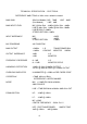
TECHNICAL SPECIFICATION - ELECTRICAL REFERENCE 0dB=775mV at 1kHz unless otherwise stated. MAX GAIN (Mic/Line Module) MIC 70dB (Line Module) LINE 6dB LINE 40dB MAX INPUT LEVEL MIC @ Max Gain -44dBu @ Min Gain + 6dBu LINE @ Max Gain -14dBu @ Min Gain +26dBu LINE MODULE +20dBu STEREO-RETURN +18dBu INPUT IMPEDANCE MIC LINE STEREO-RETURN MIC POWERING 48V PHANTOM MAX OUTPUT +23dBm +18dBm OUTPUT IMPEDANCE <60R <20R L-R MONITOR FREQUENCY RESPONSE 0: -1dB 0: -1.
OUTPUT LIMITER THRESHOLD RATIO ATTACK RELEASE CURRENT CONSUMPTION 130mA (4 INPUT) 12V DC SUPPLY 7 +8dB 7:1 4mS 250mS
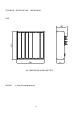
TECHNICAL SPECIFICATION - MECHANICAL SIZE ALL DIMENSIONS IN MILLIMETRES WEIGHT 2.
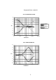
EQUALISATION CURVES AD 114 HIGH AND LOW EQ 20 15 10 5 LF BOOST LF CUT dB 0 HF BOOST HF CUT -5 -10 -15 -20 10 100 1000 10000 100000 FREQUENCY AD 114 MID EQ AND HPF 20 15 10 5 dB 0 -5 -10 -15 -20 10 100 1000 10000 FREQUENCY 9 100000
BLOCK DIAGRAM 10
RET CONNECTOR PANEL (4) MULTIWAY (3) (5) (1) L R (1) (2) (3) (4) (5) AD 114 1 2 3 4 (2) 11 Stereo output XLRs (L & R) Mic/Line input XLRs External DC power input Stereo-return jack Subsidiary connector
All input and output impedances and levels are to be found in the TECHNICAL SPECIFICATION. All inputs to, and outputs from AD114 are to be found on the connector panel except for the monitor output, which is mounted on the bottom panel facing the operator. Module connector (2) accepts balanced microphones and balanced line-level inputs. XLR (input & output) Pin 1 Pin 2 Pin 3 Shield Signal + Signal – In the case of unbalanced line-inputs and outputs, pins 1 & 3 should be connected.
A three-position rocker switch BATT/EXT selects either internal batteries or an external DC source. Power to the mixer is confirmed by the MIX ON LED on the power module. External powering of the mixer is via a 4-pin XLR (3). XLR Pin 1 Pin 2 OV NC Pin 3 Pin 4 NC 9V - 15V DC A suitable external power supply is Audio Developments’ AD100-15, but any external DC source must be capable of delivering 600mA at 12V.
MICROPHONE/LINE INPUT MODULE OFF 48V PH MIC LN 20 (1) Microphone power 30 (2) Microphone/Line select 40 50 60 70 (3) Input-gain control ∅1 ∅2 (4) Phase change OFF 150 90 - HF + (11) High-frequency control (5) High-pass filter EQ - IN MF + (12) Mid-frequency control (6) EQ Selector - L LF + (13) Low-frequency control R (7) Routeing Select 0 PFL 5 (8) Pre-fade listen (9) PFL indicator LED 10 OL 15 20 (10) Overload indicator 30 40 50 ∞ 14 (14) Channel fader
The Microphone/Line input module functions are as follows: Switch (1) selects 48V phantom power for condenser microphones. Powering may be selected before or after connecting the microphone, but switch off all powering on unterminated modules to ensure unconditional stability of the mixer. For complete safety of external equipment, switch off microphone power before connecting a line-level signal. Phase change (4) is pre transformer and operates on microphone and line inputs. ∅1 is the normal position.
OUTPUT MODULE (11) Meter Illumination (1) Meter (12) Microphone level (3) Slate (13) Return level control (4) Internal microphone (5) Line-up tone (14) Monitor return select (6) Limiter link (15) Monitor left (7) Output limiters Matrix (16) Monitor right (8) Limiter LEDs (17) Monitor level control (9) Output fader 16
This module controls the level of main and monitor output signals and metering of the output signals. Calibration is achieved when the stereo output level control (9) is at maximum. (1) Meter reads left output, right output and PFL level. Battery status is read on the meter and the meters may be illuminated by ILL (11) overuse of this function will rapidly drain the batteries. When the internal voltage drops below a safe operating level the battery status reading is at the lower limit of the BATT mark.
ADJUSTMENTS AND CALIBRATIONS Line-up-tone oscillator - the preset (VR3) that adjusts its level at the output of the mixer is mounted on the output module printed circuit board. Meter Calibration The meter has only one calibration preset potentiometer per indicator bar; which controls the adjustment of the level of the reading in relationship to the signal being measured. All other aspects of the meter specification are taken care of within the software and fixed values in the circuitry.
Main-output limiters - calibration involves two presets per output. Using the 'L' output as the example … Biasing and threshold are adjusted as follows: VR5 biases the limiter circuit to the point of correct operation and VR4 sets the threshold. (Labelled SET 0 and THR respectively.) With no signal present, VR5 should be adjusted to give a reading in the range -1.5V to -2.5V at PIN 14 of IC 2. VR4 should be adjusted to give a reading in the range -2.5V to -3.5V at PIN 10 of IC2.
POWER SUPPLY UNIT TYPE AD100-015 The AD100-015 mains POWER SUPPLY UNIT is suitable for driving most of AUDIO DEVELOPMENTS’ range of portable audio mixers. This PSU is a single-rail device providing 1A of current at +14V DC potential and is used as a substitute for battery power with mixers containing an internal DC-DC converter. The AD100-015 may be powered from either a 110/120V AC source or a 220v/240V AC source. Operating the equipment at the wrong voltage could be hazardous.
CUSTOMER NOTES AND FACTORY MODIFICATION 21
TECHNICAL LIBRARY 22
MIC/LINE PARTS LIST Item 1 2 3 4 Part Number Qnty CAD Part Ref. Ref. Designator 74-130-001 74-120-010 74-920-001 18-001-256 1 1 1 6 AMP-064V IC2 AMP-393V IC5 AMP-MIC AMP-MIC/1 CAPCER100ND C35, C36, C37, C38, C39, C40 5 18-001-321 1 CAPCERU#47P C28 6 18-015-507 3 CAPELEC1.0G1 C3, C4, C25 7 18-015-411 2 CAPELEC4.7E1 C15, C16 8 18-013-022 1 CAPELEC102B1 C8 9 18-045-019 2 CAPPES470N-H C2, C32 10 18-001-241 2 CCU#2N2 C43, C44 11 18-001-227 1 CCU#150P C21 12 18-010-808 1 CEA4.
44 70-031-108 45 70-031-112 46 70-031-120 47 48 49 50 51 52 70-031-132 70-031-136 82-257-801 81-217-502 81-227-502 86-010-101 R55, R57, R58, R63 1 RESM1/8#33K R48 4 RESM1/8#47K R43, R45, R66, R67 6 RESM1/8#100K R34, R36, R44, R47, R49, R51 1 RESM1/8#330K R40 1 RESM1/8#470K R41 1 ROT1061 SW5 4 TOG06 S1, S2, S4, S6 1 TOG08 S3 1 TXA-A187A1C T1 24
OUTPUT L/H BOARD PARTS LIST Item Part Number Qnty CAD Part Ref. Ref.
OUTPUT R/H BOARD PARTS LIST Item Part Number Qnty CAD Part Ref. Ref. Designator 1 74-120-002 2 74-130-001 3 74-920-000 2 AMP-062V IC1, IC3 2 AMP-064V IC2, IC6 4 AMP-LIB LIB1, LIB2, LIB3, LIB4 4 18-001-217 2 CAPCER22P-G C8, C50 5 18-001-245 2 CAPCERU#4N7 C6, C61 6 18-001-213 2 CAPCERU#10P C14, C55 7 2 CAPCERU#22P C9, C51 8 18-015-507 4 CAPELEC1.0H1 C12, C13, C56, C57 9 18-015-411 2 CAPELEC4.
30 70-031-104 31 70-031-112 32 70-031-118 33 70-031-120 34 70-031-128 35 36 37 38 70-031-144 32-050-052 32-050-074 72-012-110 R85, R89 1 RESM1/8#22K R65 15 RESM1/8#47K R4, R8, R15, R29, R39, R56, R57, R58, R59, R62, R63, R64, R81, R94, R99 2 RESM1/8#82K R13, R83 10 RESM1/8#100K R5, R6, R22, R36, R46, R60, R66, R90, R100, R101 6 RESM1/8#220K R9, R16, R25, R91, R93, R97 4 RESM1/8#1M R7, R11, R98, R103 4 TRM-CRT#100K VR4, VR5, VR6, VR7 1 TRM-CRT#220K VR10 1 ZEN-0.
CONVERTER PARTS LIST Item Part Number Qnty CAD Part Ref. Ref.
signals. Switching to the bypass (EQ) position enables immediate comparison of the original unaltered signals without the need to disturb the chosen settings. HF (2). – High frequency equalisation control giving ±12dB at 10kHz, variable slope. MF (3). – Mid frequency equalisation control centred on 2.4 kHz giving ±15dB peak and dip. LF (4). – Low frequency equalisation control giving ±10dB at 100Hz, variable turnover.
30