
Manual


33
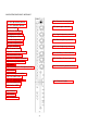
All input and output impedances and levels are to be found in the TECHNICAL
SPECIFICATION.
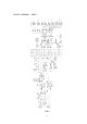
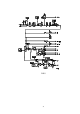
All inputs to, and outputs from AD149 are to be found on the connector panel.
Module connector (1) accepts balanced microphones, line 1, stereo left
Module connector (2) accepts balanced, line-level inputs, line 2, stereo right.
XLR (Inputs & Outputs) Pin 1 Shield
Pin 2 Signal +
Pin 3 Signal -
In the case of an unbalanced line-inputs and outputs, pins 1 & 3 should be connected.
This will not lead to a loss of level.
(When the option of separate connectors for microphone and line has been selected,
the channel output/clean-feed signal appears on a mono, unbalanced jack in the
centre of connector (2) - otherwise connector (2) carries channel output.)
Main (3) and auxiliary (4) outputs are transformer balanced, and are at line-level.
The unbalanced stereo-returns enter the mixer on two standard, ‘A’ type unbalanced
stereo jacks; L-R (5) and AUX (6).
Unbalanced monitor 1 output is on a mono, unbalanced (‘A’ type) stereo jack;
MON 1 (8).
Monitor 2 (headphones) output appears on an ‘A’ type stereo jack (9). This output is
capable of driving 25R at 0dB.
EXT 2 (7) is a mono, unbalanced jack carrying monitor signals to a second outstation.
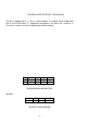
MONO UNBALANCED JACK STEREO UNBALANCED JACK
Tip Signal + Tip Left Signal
Ring Shield Ring Right Signal
Sleeve Shield Sleeve Shield
Channel insert-jack: Tip = send; Ring = return.
The 6-pin XLR connector, EXT 1 (17), carries all signals to and from an outstation.
The balanced return appears only on the headphones output.
XLR Pin 1 Shield Pin 4 Ret +
2 Send Left 5 Ret -
3 Send Right 6 Control