
Manual


49
For optimum performance at line level, this module employs a double-balanced,
instrumentation-grade input amplifier (3 x ICs) rather than the inferior differentially-
balanced amplifier (1 x IC).
Isolation between the two inputs (Line 1 and Line 2) is so high, they may remain
connected to the mixer simultaneously. Line 2 input is selected by switch (3).
Following the input amplifier is the continuously-variable, input-gain control (23) and
phase change (4).
The three high-pass filters are independent of the equaliser and are selected by
combining switches (5) and (6). HPF frequencies are to be found in the TECHNICAL
SPECIFICATION. The equaliser is identical with that in the microphone/line module
and is engaged by EQ (9).
For convenience in post-production, and in order that external processing equipment
may remain connected to the module, an insert in/out switch has been included -
INST (17).
The channel output can be selected to pre fader via the DIL switch on the main PCB.
(Refer to page 74)
Extra gain in pre-fader auxiliaries has been deemed unnecessary in post-production
and has not been included in this module - auxiliary level controls are attenuators
only, whether the source is pre or post fader. Otherwise, the auxiliary section is
identical with that in the microphone/line module.
Routeing to main output (channel mute) - L-R (16), routeing to monitor 1 - MON (18),
PFL and LED - (19) and (20), overload LED - (21), panpot (29) and clean feed are all
identical with those in the microphone/line module.
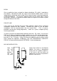
Mono line modules have been designed to be used in pairs and situated in the mixer
frame in positions 1/2, 3/4, 5/6 etc. On the mother board, between these positions
are small plug-in PCBs carrying the two encoding/decoding matrix amplifiers and
which are engaged by MTX 1 (2) and/or MTX 2 (15) on BOTH modules of the stereo
pair.