
Manual


70
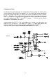
COMMUNICATIONS
In order that the sound operator can communicate with any output, the safety switch
(Comms Master) ON (29) must be selected: L-R (18) routes the internal microphone
to the main output and AUX (19) routes the internal microphone to both auxiliary
outputs. [Switches (18) and (19) have a momentary action, ie they are non-latching.]
EXT 1 (17) and EXT 2 (32) route the signal from the internal microphone to replace
any signal appearing on EXT 1 and EXT 2 outputs. The level of the internal
microphone is controlled by preset (31).
Communication from EXT 1 to the sound operator is initiated at the outstation and
feeds the PFL mix busses. Like other PFL signals, it is under logic control and
replaces any other signal on monitor 2 output, ie the operator's headphones.
The level of this return signal is controlled by potentiometer PFL (16).
FIG 16