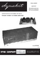
SERIAL NUMBER 14635013 This number must be mentioned in all communications concerning Dynakit. INSTRUCTIONS FOR THE ASSEMBLY AND USE OF DYNAKIT STEREO 35 POWER AMPLIFIER Price $1.
CONTENTS Description 3 General Wiring Practice 4 Mechanical Assembly 5 Wiring instructions 6 240-Volt Transformers 9 Installation 9 In Case of Trouble 10 Part List 11 Schematic Diagram Back Cover S P E C I F I C AT I O N S Power Output: 35 watts continuous, 45 watts IHFM Music Power (both channels) Frequency Response: ±1db from 10 cps to 40,000 cps. Power Response: 20 cps to 20,000 cps without exceeding 1% distortion within 1 db of 17,5 watts each channel.
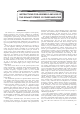
INSTRUCTIONS FOR ASSEMBLY AND USE OF THE DYNAKIT STEREO 35 POWER AMPLIFIER DESCRIPTION The Stereo 35 is a dual power amplifier of deceptively simple appearance and circuitry. Behind its seemingly conventional design is an extremely sophisticated circuit configuration representing the most recent advances in power amplifier engineering and construction.
GENERAL WIRING PRACTICE Assembly of the Stereo 35 is exceptionally simple when compared to that the other kits. The circuit board are supplied with all components mounted, and the remaining parts arranged on the chassis in an open, uncluttered way that makes wiring quick and easy. The construction of the Stereo 35 should take no more than few hours. When you unpack the kit, check the components against the parts list first.
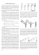
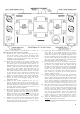
C H E C K P I C TO R I A L D I A G R A M S # 1 A N D # 3 BEFORE AND AFTER DOING EACH STEP. 1( ) Mount the two 3-screw terminal strips on the outside of the chassis in the cutouts provided, using #4 screws, nuts and lockwashers (the smallest size supplied). The pictorial diagram shows the correct orientation of the terminal strips. 2( ) Mount the fuse holder in its cutout, fastening it in place with the circular brass threaded ring.
WIRING INSTRUCTIONS Refer to pictorial diagram #2 before and after each step. After making a connection, bend (dress) each lead or wire so that it follows the path shown in the diagram as closely as possible. After all connections have been made to a terminal and it is soldered cut off any excess wire. 1( ) Begin with the group of five leads from the power transformer PA-774, all of which come through the hole in the chassis opposite of fuse holder.
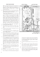
15( ) Cut the black, orange and yellow leads of the LEFT output transformer to 3½" long. Twist all three of these leads together, and connect the black lead to lug C of the LEFT 3-screw terminal strip. 16( ) Connect the orange lead to lug 8 of the LEFT 3-screw terminal strip (S). RIGHT output transformer. Connect the blue lead to pin #7 of V-6 on the RIGHT circuit board (S). 21( ) Connect the green lead to pin #9 of V-6.
REFER TO PICTORIAL DIAGRAM #3. 26( ) Connect one end of the 6800-ohm (blue, gray, red), 1-watt resistor to lug #2 (square symbol) of the filter capacitor. Connect the other end to lug #3 (triangle symbol) of the capacitor. The resistor leads should be cut to permit mounting exactly as is shown in the diagram. 27( ) Connect one end of the 50-ohm, 5-watt resistor to lug #1 (curved line symbol) of the filter capacitor. Connect the other end to lug #2 (square symbol) of the capacitor (S).
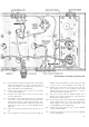
53( ) Connect one end of a 1¼" wire to pin #9 of V-3 on the LEFT circuit board (S). Connect the other end to eyelet #11 (S). 54 ( ) Connect one end of a 1" bare wire to pin #2 of V-3 on the LEFT circuit board (S). Connect the other end to eyelet #9 (S). 55( ) Connect one end of another 1" bare wire to pin #2 of V-2 on the LEFT circuit board (S). Connect the other end to eyelet #8 (S). 56( ) Connect one end of a 1" wire to the long lug of the LEFT input socket (S). Connect the other end to eyelet #1 (S).
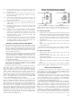
The Stereo 35 may also be used with an FM tuner without need for a preamplifier, provided that the tuner is equipped with a volume control and switched a.c. outlet, and has an out put of at least 1 volt. The loud speakers chosen may be of any impedance or efficiency, since the Stereo 35 has sufficient power reserve beyond that usually required for home listening so that no lack of volume is likely to be observed, even with relatively inefficient speakers.
If hum and noise are present to any unusual degree, first remove the inputs plugs from the Stereo 35, and replace them with short-circuited input plugs (or temporarily connect a jumper between eyelets 1 and 2 on each circuit board). If the hum and noise become virtually inaudible, the amplifier is probably working properly, and the cause should be sought elsewhere in the system.