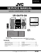
UX-G6/FS-G6 SERVICE MANUAL MICRO COMPONENT SYSTEM UX-G6/FS-G6 Area Suffix (UX-G6) UB ............. Hong Kong UP ..................... Korea U ............... Other Areas OPEN/CLOSE STANDBY/ON M I C R O C O M P O N E N T S Y S T E M U X - G 6 R AUX FM/AM MULTI JOG VOLUME MOS - FET Area Suffix (FS-G6) J ......... U.S.A./ Canada REMOTE CONTROL RM-SUXG6E PANEL OPEN/CLOSE DIMMER 1 B I T ACTIVE BASS EX.
UX-G6/FS-6G Safety Precautions 1. This design of this product contains special hardware and many circuits and components specially for safety purposes. For continued protection, no changes should be made to the original design unless authorized in writing by the manufacturer. Replacement parts must be identical to those used in the original circuits. Services should be performed by qualified personnel only. 2. Alterations of the design or circuitry of the product should not be made.
UX-G6/FS-G6 Important for laser products 5.CAUTION : If safety switches malfunction, the laser is able 1.CLASS 1 LASER PRODUCT to function. 2.DANGER : Invisible laser radiation when open and inter 6.CAUTION : Use of controls, adjustments or performance of lock failed or defeated. Avoid direct exposure to beam. procedures other than those specified herein may result in 3.CAUTION : There are no serviceable parts inside the hazardous radiation exposure. Laser Unit. Do not disassemble the Laser Unit.
UX-G6/FS-G6 Preventing static electricity Electrostatic discharge (ESD), which occurs when static electricity stored in the body, fabric, etc. is discharged, can destroy the laser diode in the traverse unit (optical pickup). Take care to prevent this when performing repairs. 1.1. Grounding to prevent damage by static electricity Static electricity in the work area can destroy the optical pickup (laser diode) in devices such as DVD players.
UX-G6/FS-G6 Attention at repair reception < ATTENTION > When this model is repaired, a part of unit of "UX-G6/FS-G6" is necessary. A necessary unit is described to rear panel. Please keep the unit from the customer together when you repair this model.
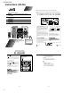
UX-G6/FS-G6 Instructions (UX-G6) Mains (AC) Line Instruction (not applicable for Europe, U.S.A., Canada, Australia and U.K.) Instrucción sobre la línea de la red (CA) (no aplicable para Europa, EE.UU., Canadá, Australia, ni el Reino Unido) MICRO COMPONENT SYSTEM UX-G6 Consists of AX-UXG6, XT-UXG6, TD-UXG6, and SP-UXG6. STEREO AMPLIFIER AX-UXG6 COMPACT DISC/TUNER UNPLUG MAINS (AC) CORD FROM WALL OUTLET,WHEN CONNECTING THIS. XT-UXG6 STEREO AMPLIFIER MODEL NO. AX-UXG6 SYSTEN NO.
UX-G6/FS-G6 IMPORTANT FOR LASER PRODUCTS IMPORTANTE PARA PRODUCTOS LÁSER Caution: Proper Ventilation To avoid risk of electric shock and fire, and to prevent damage, locate the apparatus as follows: 1 Front: No obstructions and open spacing. 2 Sides/ Top/ Back: No obstructions should be placed in the areas shown by the dimensions below. 3 Bottom: Place on the level surface. Maintain an adequate air path for ventilation by placing on a stand with a height of 10 cm or more.
UX-G6/FS-G6 Front Panels Buttons behind the sliding panel Front Panels AX-UXG6 OPEN/CLOSE STANDBY/ON 1 AX-UXG6 Stereo Amplifier M I C R O C O M P O N E N T S Y S T E M 4 U X - G 6 5 6 2 AUX FM/AM 3 MULTI JOG VOLUME MOS - FET 7 1 2 3 4 5 6 7 Stereo Amplifier 1 2 34 56 78 9p button and STANDBY/ON lamp (11)* MULTI JOG dial FM/AM button (14)* OPEN/CLOSE button (13)* Display window VOLUME dial (12) AUX button (13, 24)* DISPLAY /CHARA.
Continued Continued Connecting MD Recorder XM-G6 Connecting Antennas You can also connect the MD recorder XM-G6 (not supplied), specifically designed for UX-G6. This unit will complete UX-G6 micro component system. When you connect and use this unit, refer to the Instructions supplied with it for details. Supplied FM antenna AX-UXG6 Connecting Speakers AM antenna You can connect the speakers using the speaker cords.
Common Operations PANEL OPEN/CLOSE REMOTE CONTROL RM-SUXG6E PANEL OPEN/CLOSE DIMMER ACTIVE BASS EX. CLOCK/TIMER TREBLE BASS Continued (standby/on) ACTIVE BASS EX. SLEEP FM MODE BASS AUTO PRESET TREBLE STANDBY/ON OPEN/CLOSE TITTLE/EDIT When you unplug the AC power cord or if a power failure occurs The clock is reset to “0:00” right away, while the tuner preset stations will be erased in a few days.
UX-G6/FS-G6 English Preset Station You are possibly not allowed to use the feature until the station presetting completes. In some cases, test frequencies have been already memorized for the system since the factory examined the preset station features before shipment. This is not a malfunction. 5 The tuned station in step 1 is now stored in the preset channel selected in step 3. Buttons behind the sliding panel BASS TITTLE/EDIT < Press SET button.
Playing Back a Tape Continued Playing at Random — Random Play Repeating Tracks — Repeat Play The tracks of the loaded CD will play in no special order (at random) when you select this mode. You can have the entire disc, the programed tracks, or the individual track repeat as many times as you like. DISPLAY /CHARA. 1 2 Place a CD. If the current playing source is not the CD, press 6 (play/pause) button on the CD unit, then 7 (stop) button before going to the next step.
REC indicator lights red to show the recording pause mode, and “TAPE REC” appears in the display window as follows, or Dolby B NR Press DOLBY B NR button before recording to reduce frequency response noise. When the tape is played back later, also press the button with its lamp lit. Synchronized Recording from a CD 1 Recording in Auto Reverse 1 To change the recording source You cannot change the selected source during the recording pause mode.
Continued 5 6 Rotate MULTI JOG dial (< / > button on the remote control also available) to select the minute of the timer-off time, then press SET button. Rotate MULTI JOG dial (< / > button on the remote control also available) to select the source, then press SET button. TUNER TUNER (MD) CD FM AM (AUX TAPE AUX DIGITAL) TUNER FM: Tunes into a preset FM station. Go to step 7. TUNER AM: Tunes into a preset AM station. Go to step 7. CD: Plays a CD. Prepare a CD, then go to step 7.
Troubleshooting Specifications If you are having a problem with your system, check this list for a possible solution before calling for service. If you cannot solve the problem from the hints given here, or the units has been physically damaged, call a qualified person, such as your dealer, for service. Stereo Amplifier Symptom No sound is heard. Poor radio reception. Unable to record onto a tape. Possible Cause • Action • • Connections are incorrect, or loose. Headphones are connected.
UX-G6/FS-G6 << M E M O >> 1-16
UX-G6/FS-G6 AX-UXG6 2-1
UX-G6/FS-G6 Disassembly method (AX-UXG6) B Removing the top cover (See Fig.1) 1. Remove the two screws A and the four screws B attaching the top cover. 2. Remove the top cover from behind in the direction of the arrow while pulling the sides outward. A 2 B Fig. 1 Removing the front panel assembly (See Fig.2 to 5) 1. Pull out the lower part of the front panel assembly manually as shown in Fig.2 and 3. 2. Remove the two screws C with collars attaching the front panel assembly. 3.
UX-G6/FS-G6 Front sub panel assembly Removing the front sub panel assembly (See Fig.6 to 8) • Prior to performing the following procedure, remove the top cover and the front panel assembly. CN704 1. Disconnect the card wire from connector CN704 on the back of the front sub panel assembly. Fig. 6 2. Remove the two screws D on the bottom of the body. Joint b 3. Release the joint "b" on the bottom and the two joints "c" on both sides of the body, and remove the front sub panel assembly toward the front.
UX-G6/FS-G6 Regulator board Removing the regulator board (See Fig.10) • Prior to performing the following procedure, remove the top cover. 1. Disconnect the card wire from connector CN908 on the main board. 2. Disconnect the harness from connector CN906 on the main board. G G CN906 Main board CN908 Fig. 10 3. Remove the two screws G attaching the regulator board. Power transformer Removing the transformer assembly (See Fig.11) • Prior to performing the following procedure, remove the top cover.
UX-G6/FS-G6 Removing the main board and the heat sink (See Fig.11 to 18) • Prior to performing the following procedure, remove the top cover and the rear cover. 1. Disconnect the harness or card wire from connector CN903, CN904, CN905, CN906, CN907 and CN908 on the main board. CN907 CN906 I CN908 CN905 J I CN903 Heat sink CN904 Main board Fig. 12 2. Remove the two screws I attaching the main board and the screw J attaching the heat sink. 3.
UX-G6/FS-G6 Removing the slide gear motor assembly (See Fig.19 to 21) • Prior to performing the following procedure, remove the top cover and the regulator board . 1. Disconnect the harness from connector CN907 on the main board. 2. Remove the two screws O attaching the slide gear motor assembly. O Slide gear motor assembly O Main board CN907 Fig. 19 3. Remove the belt from the motor pulley. 4. Remove the two screws P and the screw Q attaching the motor assembly. Belt P Motor pulley Fig.
UX-G6/FS-G6 Front panel assembly Removing the front board. (See Fig.22 to 24) • Prior to performing the following procedure, remove the top cover and the front panel assembly. 1. Remove the seven screws R attaching the front panel cover on the back of the front panel assembly. 2. Remove the four screws S attaching the front board. 3. The multi-jog dial and the volume dial on the front panel assembly also comes off when removing the front board. Volume dial Multi-jog dial Fig.
UX-G6/FS-G6 Description of major ICs LB1641 (IC901) : DC Motor driver 1. Pin Layout 1 2 3 4 5 6 GND OUT1 P1 VZ IN1 7 8 9 IN2 VCC1 VCC2 P2 10 OUT2 2.
UX-G6/FS-G6 UPD780023 (IC701) : System control 1.Pin layout 2.Key matrix ~ ~ 64 ~ 49 1 48 16 33 17 ~ 32 KEYO1 KEYI1 KEYI2 KEYI3 KEYI4 PLAYMODE RECMODE KEYO2 CLOCK/TIMER SET CANCEL KEYO3 TITLE/EDIT DISPLAY/CHARA. ENTER 3.Pin function Pin No. 1,2 3,4 5 6 7 8 9 10 11 12 13 14 15 16 17 18 19 20 21 22 23 24 25 26 27 28~32 33 34 35 36 37 38 39 40,41 42 43~46 47~49 50~59 60 61 62 63 64 Symbol JOG1A,B JOG2A,B CLOSE OPEN CLOSESW OPENSW VSS0 VDD0 FLOFF FLBK FLLAT FLSOUT FLSLK COMMAND STATUS CLK READY P.
2-10 FL DISPLAY DI701 JOG1:JS701 JOG2:JS702 OPERATION SWITCH S7001~S7004 LED D7001~D7004 D7007 CN701 PANELKEY JOG1A,B JOG2A,B SYSTEM CONTROL IC701 OSC X7001 8MHz CN702 POWERLED STBYLED JOG1BLU JOG2BLU KEYI1~4 KEYO1~3 CN710 FW701 OPERATION SWITCH S7005~S7014 SW911 OPENSW OPEN/CLOSE LM DOOR OPEN/CLOSE MOTOR M9001 FW904 CN907 CLOSESW SW912 CN101 IC101 MOTOR DRIVER IC901 CN101 RESET L/R IN COMMAND CLK STATUS AXRESET READY INH CN909 Connect to CN431 (XT-UXG6) SPK R SUB WOOFER OUT
UX-G6/FS-G6 XT-UXG6 2-11
UX-G6/FS-G6 Disassembly method (XT-UXG6) Top cover B Removing the top cover (See Fig.1) 1. Remove the two screws A and the four screws B attaching the top cover. Remove the top cover in the direction of the arrow while pulling it. B A 2 B Fig. 1 CN501 CN451 System control board Removing the front panel assembly (See Fig.2 to 4) • Front panel assembly Prior to performing the following procedure, remove the top cover. Tie band 1. Cut the tie band fixing the harness on the side of the body.
UX-G6/FS-G6 Removing the front panel assembly (See Fig.5 and 6) • E E Rear panel Prior to performing the following procedure, remove the top cover. 1. Remove the seven screws E attaching the rear panel on the back of the body and release the two joints "c" on both sides while moving the rear panel upward. joint c joint c E E Fig. 5 2. Disconnect the harness from connector CN431 on the main & CD servo board.
UX-G6/FS-G6 CN451 Removing the analog in/digital out board and the relay board (See Fig.8 to 10) • Prior to performing the following procedure, remove the top cover, the rear panel and the system control board. 1. Cut the tie band fixing the harness on the side of the body. Disconnect the harness from connector CN451 on the analog in/digital out board and remove the screw G attaching the analog in/ digital out board. Analog in/digital out board Tie band G Fig. 8 CN451 CN455 2.
UX-G6/FS-G6 Removing the CD mechanism assembly main & CD servo board (See Fig.12 to 14) • Prior to performing the following procedure, remove the top cover, the front panel assembly, the rear panel, the system control board and the analog in/digital out board. Main & CD servo board CD mechanism assembly J 1. Remove the three screws I attaching the CD mechanism assembly and the screw J attaching the main & CD servo board.(The CD mechanism assembly will be detached together with the main & CD servo board.
UX-G6/FS-G6 << CD Mechanism section >> Removing the traverse mechanism CD tray 1. Remove the tray stopper screw "A" on the CD tray 2. The CD tray is drawn out in the direction of the arrow. Tray stopper screw A Hole by which driver is inserted * When the mechanism is locked to the CD tray, the lockof the CD tray comes off when the driver etc. are inserted in the hole in the bottom of the mechanism, and turns counterclockwise and the CD tray is drawn out. 3.
UX-G6/FS-G6 Removing the spindle motor 1. Remove the traverse mechanism 2. The turntable is removed from the spindle motor, and remove two screws D which is the fixation of the spindle motor. 3. Remove the screw which is the fixation of the spindle motor and the feed motor, and solder on the substrate is removed. D Turntable How to install spindle motor 1. The shaft of the spindle motor is passed from the lower side of the mechanism base. 2. Two screws are installed in the spindle motor by same strength.
UX-G6/FS-G6 Flow of functional operation until TOC read Check Point Play Key Power ON Slider turns REST SW ON. Confirm that the voltage at the pin5 of CN440 is "H"\"L"\"H". Automatic tuning of TE offset Check that the voltage at the Laser ON pin40 of IC461 is + 5V? Detection of disc Automatic tuning of Focus offset Automatic measurement of Focus S-curve amplitude Confirm that the Focus error S-cuve signal at the pin28 of IC462 is approx.
UX-G6/FS-G6 Maintenance of laser pickup Replacement of laser pickup (1) Cleaning the pick up lens Before you replace the pick up, please try to clean the lens with a alcohol soaked cotton swab. (2) Life of the laser diode When the life of the laser diode has expired, the following symptoms will appear. Turn off the power switch and,disconnect the power cord from the ac outlet. Replace the pickup with a normal one.(Refer to "Pickup Removal" on the previous page) 1.
UX-G6/FS-G6 Description of major ICs AN8806S (IC462) : RF & Servo AMP 1.Pin layout PD LD LDON LDP VCC RFRF OUT RF IN C.AGC ARF C.ENV C.EA CS BDO BDO CS BRT OFTR /NRFDET GND 36 35 34 33 32 31 30 29 28 27 26 25 24 23 22 21 20 19 1 2 3 4 5 6 7 8 9 10 11 12 13 14 15 16 17 18 PDAC PDBD PDF PDE PDER PDFR TBAL FBAL EFEF OUT TETE OUT CROSS TE BPF VDET LD OFF VREF ENV 2.
UX-G6/FS-G6 3. Pin function Pin No. Symbol I/O 1 PD I APC amp input terminal 2 LD O APC amp output terminal 3 LD ON I APC ON/OFF control terminal 4 LDP -- Connect to ground 5 VCC -- Power supply 6 RF- I Inverse input pin for RF amp 7 RF OUT O RFamp output 8 RF IN I 9 C.AGC I/O Description RF input Connecting pin of AGC loop filter 10 ARF O RF output 11 C.ENV I/O A capacitor is connected to this terminal to detect the envelope of RF signal 12 C.
UX-G6/FS-G6 BA6897FP (IC463) : 4channel driver TC9164AN (IC432) : Analog switch 1.Function Switch to On/Off of S1 to S8 by control of LSI. D.BUF CH1-OUTA 1 28 GND D.BUF CH1-OUTB 2 2.Terminal Lay out & Block Diagram 27 CH4-OUTA TC9164AN D.BUF 3 CH1-INB 4 TEST1 5 TEST2 6 MUTE + Level shift + Level shift 26 CH4-OUTB D.BUF VSS 1 28 VDD L-S1 2 27 R-S1 25 CH4-INA -+ T.S.
UX-G6/FS-G6 MN35511AL (IC461) : Digital servo & Processor 1.Pin layout 20 1 21 80 40 61 41 60 2.
UX-G6/FS-G6 3.
UX-G6/FS-G6 LC72136N (IC2) : PLL frequency synthesizer 1. Pin layout XT FM/AM CE DI CLOCK DO FM/ST/VCO AM/FM 1 2 3 4 5 6 7 8 9 10 SDIN 11 22 21 20 19 18 17 16 15 14 13 12 XT GND LPFOUT LPFIN PD VCC FMIN AMIN IFCONT IFIN 2. Block diagram Phase Detector Charge Pump Reference Driver 1 18 22 19 20 16 Swallow Counter 1/16,1/17 4bit 1/2 Unlock Detector 12bit Programmable DriverS 15 12 3 4 C2B I/F 5 Universal Counter Data Shift Register & Latch 6 Power on Reset 17 21 7 8 2 11 13 3.
UX-G6/FS-G6 TA2057N (IC1) : FM/AMP IF AMP & Detector 1.Block Diagrams FM IF IN AM MIX OUT Vstb AM IF IN QUAD 24 23 22 21 20 FM OUT AM OUT MPX IN 19 18 LPF 1 LPF 2 VCO 16 15 14 17 L OUT 13 REG VCO DIVIDE AM FM IF FM DET LEVEL SW AM DET AM IF AM/FM MONO SW IF BUFF AM MIX AM OSC 1 2 AM RF IN AM S.SENS 3 FM S.SENS MUTE DECODE AGC BUFF IF REQ SW TUN LED ST LED 4 5 6 7 8 9 10 11 12 AM OSC AM OSC OUT Vcc AGC GND IF OUT /REQ TUN LED ST LED R OUT 2.
UX-G6/FS-G6 TA7439 (IC435) : Rear/center volume 1.Pin layout 1 30 2 29 3 28 4 27 5 26 6 25 7 24 8 23 9 22 10 21 11 20 12 19 13 18 14 CSL DIG GND TREBLE(R) TREBLE(L) MIN(L) MOUT(L) BOUT(L) BIN(L) BOUT(R) BIN(R) MOUT(R) MIN(R) INR MUXOUTR INL 17 TREBLE(L) MIN(L) MOT(L) BIN(L) BOUT(L) 2.
UX-G6/FS-G6 UPD784214AFG501 (IC501) : Sysem controller 1.Pin layout 50 ~ 80 ~ 51 ~ 81 100 31 1 ~ 30 2. Pin function Pin Symbol I/O No.
,T CN506 CN505 TO TUNER SECTION CN440 TO W451 CN508 CN502 BLKCK RESTSW SUBQ LSIRST SQCK STAT MLD MDATA CN503 CLK COMMAND STATUS READY SYSTEM CONTROL IC501 FTU CN501 REMOTE CONTROL IC502 HEADPHONE J5001 OPERATION SWITCH S5001~S5003 W511 CN434 TUO L/R AUX L/R ASWO L/R CN452 SDA SCL L/R IN ELECTRIC VOLUME IC435 AUX IN J4301 L/R OUT ASOW L/R DOUT DIGITAL OUT J4302 Connect to CN909 (AX-UXG6) CN455 HEADPHONE AMP.
UX-G6/FS-G6 << M E M O >> 2-30
UX-G6/FS-G6 TD-UXG6 2-31
UX-G6/FS-G6 Disassembly method (TD-UXG6) Top cover B Removing the top cover (See Fig.1) 1. Remove the two screws A and the four screws B attaching the top cover. B A x2 2. Remove the top cover from behind in the direction of the arrow while pulling the sides outward. B Fig. 1 Removing the front panel assembly (See Fig.2 to 5) • Front panel assembly Prior to performing the following procedure, remove the top cover. 1.
UX-G6/FS-G6 E Removing the rear panel Rear panel (See Fig.6 and 7) • Prior to performing the following procedure, remove the top cover. 1. Remove the three screws E attaching the rear panel on the back of the body and release the two joints "c" on both sides while moving the rear panel upward 2. Disconnect the harness from connector CN633 on the main board.
UX-G6/FS-G6 Connector on the motor board Removing the loading mechanism board/ Dolby board (See Fig.9) • Prior to performing the following procedure, remove the top cover and the rear panel. CN632 1. Disconnect the harness from the connector on the motor board in the cassette mechanism. Then disconnect the loading mechanism board from connector CN634 on the main board. Dolby board Main board 2. Disconnect the Dolby board from connector CN632 and CN636 on the main board.
UX-G6/FS-G6 <> Detaching the cassette loading mechanism (Fig. 1 to 3) 1. Turn the loading drive gear in the direction shown by the arrow so that the head relay board can be removed. 2. Remove the screw A securing the head relay board (to protect the head wire). 3. Remove the two screws B securing the capstan motor bracket. 4. Remove the screw D securing the cassette stabilizer, and detach the stabilizer by pressing it from the side the securing screw is on. 5.
UX-G6/FS-G6 Detaching the capstan motor (Fig. 4) 1. Disconnect the capstan motor wiring. 2. Remove the two screws F securing the capstan motor. F Fig. 4 F Detaching the mechanism (Fig. 5 to 11) 1. Head block Remove the two screws G securing the head block (when installing, attach to the return gear arm). 2. Pinch roller assembly (1) Remove the pinch roller return spring (used to prevent particle build-up). (2) Release the hook securing the pinch roller arm and pull the assembly up. 3.
UX-G6/FS-G6 4. Leaf switch replacement Remove the two screws H securing the leaf switch board. H Unsolder Fig. 8 5. Mechanism base (1) Pull out the reel disk. (2) Detach the brake arm. Pull up the brake arm by releasing the stopper on the brake arm shaft. (3) Remove the four switches I securing the mechanism base unit. (4) Pull out the reel idle gear. (5) Turn the unit over and remove the screw J. J Guide Reel idle gear I I I I Detaching the flywheel H Fig. 9 C washers washers 1.
UX-G6/FS-G6 Assembling (Figs. 11 to 13) 1. 2. 3. 4. 5. Set the cam gear in the position shown in the figure. Set the spring as shown in the figure. Set the solenoid plunger (shaft). Attach to the mechanism base. Slide the head return slider (white plastic) in the direction shown by the arrow to position the stud. 6. Check the positioning of the plunger. 7. Set the cam gear with the screw (K). 8. Turn the cam gear and make sure that the headbase moves back and forth. Turn Cam gear K Fig.
UX-G6/FS-G6 Main adjustment 1.Measuring instruments required for adjustment (1) Low frequency oscillator This oscillator should be capable of outputting 0dB (0.775V) at the 600W terminal at an oscillation frequency of 50 - 20kHz. (2) Attenuator (Impedance: 600 ) (3) Electronic voltmeter (4) Standard tapes for measurement VT712 (for measuring the tape speed and wow flatter) VT724 (Reference level) (1kHz) TMT735 (for measuring the playing (playback) frequency characteristics) (1kHz and 12.
UX-G6/FS-G6 Procedures for adjusting the mechanism section Caution for Changing the Head Remove the screw provided from right above the head. At this time, peel the screw locks around the head by using a sharp-pointed device. Moreover, use the screw driver matching the corresponding screw. Items 2-40 Adjusting position Adjusting position Reference value 1 Adjustment of 1. Connect the voltmeter to the head azimuth [LINE OUT] terminal. 2. Play the test tape VT705 (12.5kHz). 3.
UX-G6/FS-G6 Procedures for adjusting the electrical circuit The following adjustments should be performed after adjusting the tape traveling and head angles. • The sequence of adjustment should in principle be according to the following order of description. • The adjustment items denoted by asterisk should be performed whenever the head has been changed. [0dBs = 0.
UX-G6/FS-G6 Items Adjusting position Adjusting position Reference value *7 Adjustment of 1.While applying 1kHz -28.8dB L:VR614 R:VR624 recording and to the line input terminal, playing confirm that the sensitivity sensitivity level at the test point TP_____ is 0dBs. 2.While recording and playing back the above, adjust the recording signal current with VR614 (Lch) and VR624 (Rch) so that the sensitivity level becomes-25.5dBs. Normam tape: -25.5dBs 0.5dB 8 Confirmation 1.
UX-G6/FS-G6 Description of major ICs BA8221AN (IC634) : ALC VCC VCC 510K 39K VCC VCC 510K 39K VCC MUTE 1 2 3 4 5 6 7 8 RIN LIN TC GND MUTE LO RO VCC HA12136A (IC635) : Noise reduction amplifire REC IN 16 GND 15 PB IN 14 BIAS 13 PB REC/PB OUT 12 11 SW BUFFER AMP SW BUFFER AMP DET 10 REC OUT 9 SIDE CHAIN BIAS 1 REC IN 2 Vcc 3 PB IN 4 Vref 5 6 NR PB ON/OFF OUT SIDE CHAIN 7 8 DET REC OUT 2-43
UX-G6/FS-G6 MN171601AJABF (IC671) : System control 1.Pin layout ~ 32 ~ 17 16 ~ 33 2.Key matrix 48 1 49 ~ 64 KEYI0 KEYI1 KEYI2 KEYO0 REC PAUSE REVERSE DOLBY B NR KEYO1 STOP < > OPEN/CLOSE 3.Pin function Pin No. 1 2~7 8 9 10 11 12 13 14 15 16 17 18 19 20 21 22 23 24~26 27,28 29 30~32 33 34 35 36,37 38 39 40 41 42 43 44 45,46 47 48 49 50 51 52 53 54 55,56 57 58~61 62,63 64 2-44 Symbol REC/PB NC MSI NC Cro2/NORM BIAS NORM PBMUTE NC NROFF NRREC R.
OPEN CLOSE CN644 TRAY CONTROL IC673 PHOTO DETECTOR Q6734,Q6735 DETECT CAPN PLZ CMA CMB CN647 CAPSTAN MOTOR CONTROL Q6731~Q6733 TAPE SPEED VR671 Connect to CN433 (XT-UXG6) CN633 OPEN SWITCH CLOSE SWITCH DOLBY IC IC635 AUTO LEVEL CONTROL IC634 CN642 CN632 NROFF NRREC PB L/R REC L/R LED D6601~D6606 OPERATION SWITCH S6601~S6606 RECORDING AMP. IC631 PLAYBACK AMP.
UX-G6/FS-G6 Disassembly method (SP-UXG6) Removing the ornament panel assembly 1. Remove the saran board from the speaker box. (Saran board can be detached by pulling the side of saran board forward.) (See Fig.1) 2. A minus driver is inserted in the space between the ornament panel and the cabinet in the bottom part of the main body little by little. (See Fig.4) 3.A minus driver is inserted in a surrounding round of the ornament panel little by little, and the ornament panel is removed. (See Fig.
UX-G6/FS-G6 Standard schematic diagrams Power transformer section (AX-UXG6) 5 4 3 2 1 Parts are safety assurance parts. When replacing those parts make sure to use the specified one.
UX-G6/FS-G6 Main AMP. and power supply section (AX-UXG6) 5 4 3 2 CN908 Parts are safety assurance parts. When replacing those parts make sure to use the specified one.
UX-G6/FS-G6 FL Display and micom section (AX-UXG6) 5 4 3 2 1 A B C D E F G 2-49
UX-G6/FS-G6 System control section (XT-UXG6) 5 4 3 2 1 Main signal A B C D 2-50 E F G
UX-G6/FS-G6 CD Servo control section (XT-UXG6) 5 4 3 2 CD/Main signal Tape P/B signal Tape REC. signal Tuner signal MD Play signal MD REC.
UX-G6/FS-G6 Tuner section (XT-UXG6 except Ver.
UX-G6/FS-G6 Tuner section (XT-UXG6 only Ver.
UX-G6/FS-G6 Head AMP.
UX-G6/FS-G6 Dolby section (TD-UXG6) 5 4 3 2 1 Tape playback signal Tape recording signal A B C D E F G 2-55
UX-G6/FS-G6 Printed circuit boards System control & Main amplifier board (AX-UXG6) 5 4 3 2 1 A B C D 2-56 E F G
UX-G6/FS-G6 System control & Analog IN / digital OUT board (XT-UXG6) 5 4 3 2 1 A B C D E F G 2-57
UX-G6/FS-G6 CD Servo & Main board (XT-UXG6) 5 4 3 2 1 A B C D 2-58 E F G
UX-G6/FS-G6 Main board (TD-UXG6) 5 4 3 2 1 A B C D E F G 2-59
UX-G6/FS-G6 Tuner board (TD-UXG6) 5 4 3 2 1 A B C D 2-60 E F G
UX-G6/FS-G6 PARTS LIST [ UX-G6 ] AX-UXG6 XT-UXG6 TD-UXG6 * All printed circuit boards and its assemblies are not available as service parts. Area Suffix (UX-G6) UB................. Hong Kong UP......................... Korea U ..................
UX-G6/FS-G6 Exploded view of general assembly and parts list Block: No. M AX-UXG6 58 5 60 1 M M 71 67 72 60 82 60 59 83 f1 66 64 63 65 f2,g j 62 a 76 B A 15 14 12 4 61 14 12 5 C 15 D 59 2 18 15 12 12 19 13 19 FL Display board 18 11 8 19 3 E 9 4 1 3 6.5mm + - 0.1mm 8 29 (2.5mm +- 0.
UX-G6/FS-G6 Parts list (AX-UXG6 General assembly) Item Parts number Block No. M1MM Parts name Description Q'ty 1 LV10268-003A FRONT PANEL 1 2 LV41290-002A PUSH BUTTON 1 POWER PLATING 3 LV41291-002A PUSH BUTTON 1 OP/CL PLATING 4 LV41292-002A PUSH BUTTON 1 AUX PLATING 5 LV41293-002A PUSH BUTTON 1 BAND PLATING 6 LV41327-001A INDICATOR 1 7 LV31445-001A INDICATOR 2 FOR M.JOG/VOL 8 QYSBSF2608Z T.
UX-G6/FS-G6 Parts list (AX-UXG6 General assembly) Item 53 3-4 Parts number QYSBST3006Z Block No. M1MM Parts name Description Q'ty T.SCREW 2 FOR FOOT Area 54 QYSBSG3010E T.SCREW 1 FOR HEAT SINK 55 LV41621-001A BARRIER(B) 1 FOR HEAT SINK 58 LV10273-001A/S/ METAL COVER 1 59 QYSDSG3008N T.SCREW 2 M.COVER+B.CHASSIS 60 QYSDSG3008N T.SCREW 4 M.COVER+R.PANEL 61 LV20526-018A REAR PANEL 1 UP LV20526-012A REAR PANEL 1 U,UB 62 QYSDSG3008N T.
UX-G6/FS-G6 Electrical parts list (System control & Main amplifier board) Item Parts number Parts name Remarks Area Item Block No. 01 Parts number CN701 QGF1016F3-19 CONNECTOR C9108 QETC1HM-226Z CN702 QGF1016C1-19 CONNECTOR C9109 CN704 QGF1201F3-20 FFC/FPC CONNE C9110 CN711 QGA2001C1-07 7P PLUG ASSY CN901 QJK024-041504 SIN CR C-B WIRE CN903 QGA2501C3-04Z CN904 Parts name Remarks E CAPACITOR 22MF 20% 50V QETC1HM-226Z E CAPACITOR 22MF 20% 50V QDYB1CM-103Y C.
UX-G6/FS-G6 Electrical parts list (System control & Main amplifier board) Item Parts number Parts name Remarks Area Item D9109 MTZJ33C-T2 Z DIODE Q1009 D9110 MTZJ5.1C-T2 ZENER DIODE D9112 1SS133-T2 SI DIODE D9201 MTZJ3.3A-T2 D9202 Block No. Parts number 01 Parts name Remarks Area 2SC2240/GL/-T TRANSISTOR +18V Q1010 2SA970/GL/-T TRANSISTOR -18V Q1011 2SK2382 F.E.T. U,UB ZENER DIODE Q1011 2SK2381 F.E.T. UP MTZJ8.2C-T2 ZENER DIODE Q1012 2SK2381 F.E.T.
UX-G6/FS-G6 Electrical parts list (System control & Main amplifier board) Item Parts number Parts name Remarks Area Item Block No. Parts number 01 Parts name Remarks R1014 QRZ0214-472Y C RESISTOR 4.
UX-G6/FS-G6 Electrical parts list (System control & Main amplifier board) Item 3-8 Parts number Parts name Remarks R9506 QRE141J-103Y C RESISTOR 10K 5% 1/4W R9507 QRE141J-102Y C RESISTOR 1.0K 5% 1/4W R9508 QRE141J-104Y C RESISTOR 100K 5% 1/4W R9509 QRE141J-103Y C RESISTOR 10K 5% 1/4W R9901 QRZ9006-4R7X F RESISTOR 4.
UX-G6/FS-G6 << M E M O >> 3-9
UX-G6/FS-G6 Exploded view of general assembly and parts list XT-UXG6 Block: No.
UX-G6/FS-G6 Parts list (XT-UXG6 General assembly) Item Parts number Block No. M2MM Parts name Description Q'ty 1 LV10278-001A FRONT PANEL 1 2 LV31438-002A BUTTON 1 PLATING 3 LV41295-001A REMOTE LENS 1 4 LV31458-001A FRONT PLATE 1 5 6 E406971-222 LV41317-002A JVC MARK LENS(A) 1 1 7 LV41318-001A LENS(B) 1 8 LV41750-001A LABEL 1 9 QYSBSF2608Z T.SCREW 7 FOR SW PWB 10 E75896-002 FELT SPACER 2 FOR FOOT 11 QYSBST3006Z T.SCREW 3 FOR F.PANE+B.
UX-G6/FS-G6 CD mechanism assembly and parts list Block: No. M 3 M M Grease point FG-87HS (Grease to apply have to be a little for the exchange.) FG-87HS FG-87HS FG-87HS 12 EXL-M7GB Parts list (CD mechanism) Item 3-12 Block No.
UX-G6/FS-G6 CD loading base assembly and parts list FLM-120-1 Block: No. M 4 M M Grease = G-474C = EBS0006-009B FIG A 12 5 7 11 Apply grease to groove and support convex. 8 9 6 14 1 13 4 FIG A 18 18 10 21 3 16 2 16 16 17 16 19 17 20 15 Dimension gap for motor pulley 2 6.9 0.
UX-G6/FS-G6 Parts list (CD loading base) Item 3-14 Block No. M4MM Parts number Parts name Description Q'ty 1 E102357-441 C.D LOADING BAS 1 2 MMN-6F1LB8K MOTOR 1 3 E75984-001SC MOTOR PULLEY 1 4 QYSPSPT2640Z MINI SCREW 2 5 E75950-002 BELT 1 6 E75985-222SS GEAR(1) 1 7 E60912-005SS SPEED NUT 1 8 E75986-221SS C.D GEAR (2) 1 9 E75987-221SS C.
UX-G6/FS-G6 Electrical parts list (System control & Analog IN / digital OUT board) Block No.
UX-G6/FS-G6 Electrical parts list (System control & Analog IN / digital OUT board) Block No. Item 3-16 Parts number Parts name Remarks R5025 QRE141J-102Y C RESISTOR 1.0K 5% 1/4W R5026 QRE141J-103Y C RESISTOR 10K 5% 1/4W R5028 QRE141J-103Y C RESISTOR 10K 5% 1/4W R5029 QRE141J-103Y C RESISTOR 10K 5% 1/4W R5030 QRE141J-103Y C RESISTOR 10K 5% 1/4W R5031 QRE141J-101Y C RESISTOR 100 5% 1/4W R5032 QRE141J-102Y C RESISTOR 1.0K 5% 1/4W R5033 QRE141J-102Y C RESISTOR 1.
UX-G6/FS-G6 Electrical parts list (CD servo & Main board) Item Parts number Parts name Remarks Block No. Area 03 Item Parts number CN431 QGD1501C1-19 F.
UX-G6/FS-G6 Electrical parts list (CD servo & Main board) Item Parts number Parts name IC464 TA8409S IC IC502 GP1U271X RM RECIVER Remarks Block No. Area 03 Item Parts number Parts name Remarks R4228 QRE141J-102Y C RESISTOR 1.0K 5% 1/4W R4311 QRE141J-331Y C RESISTOR 330 5% 1/4W R4331 QRE141J-152Y C RESISTOR 1.
UX-G6/FS-G6 Electrical parts list (Tuner board) Item C 1 Parts number Parts name Block No. Remarks Area 04 Item Parts number Parts name NCB21HK-223X C CAPACITOR R 21 NRSA02J-224X MG RESISTOR C 3 NCB21EK-473X C CAPACITOR R 22 NRSA02J-331X MG RESISTOR C 4 NCB21HK-103X C CAPACITOR R 23 NRSA02J-270X MG RESISTOR C 5 QEK41CM-106 E.CAPA I.
UX-G6/FS-G6 Exploded view of general assembly and parts list Block: No.
UX-G6/FS-G6 Parts list (TD-UXG6 General assembly) Item Parts number Block No. M5MM Parts name Description Q'ty Area 1 LV10277-001A FRONT PANEL 1 2 LV31438-002A BUTTON 1 PLATING 3 LV31440-003A BUTTON 1 PLATING 4 LV41325-001A INDICATOR 1 5 LV31458-001A FRONT PLATE 1 6 E406971-222 JVC MARK 1 7 LV41317-002A LENS(A) 1 8 LV41318-002A LENS(B) 1 9 LV41750-001A LABEL 1 10 QYSBSF2608Z T.SCREW 7 FOR SW PWB 11 E75896-002 FELT SPACER 2 FOR FOOT 12 QYSBST3006Z T.
3-22 114 125 A 86 120 136 134 B C 73 1/2 75 66 68 57 91 97 71 72 5 91 69 4 25 138 24 23 90 83 81 2 58 27 92 1 44 119 106 22 129 19 139 45 91 65 84 21 33 128 64 91 91 39 32 40 123 41 137 42 135 141 43 136 118 90 31 88 67 20 3 124 105 29 28 94 139 52 30 36 34 37 128 79 90 139 38 139 84 111 3 90 99 141 122 128 85 90 82 80 126 121 116 126 25 24 23 22 98 26 90 100 126 112 110 17 96 133 131 139
UX-G6/FS-G6 Grease point 1. CHASSIS 94. MECHA BASE(H)ASSY CFD-005H A EM-30L EM-30L Grease is not available EM-30L EM-30L Right and left EM-30L B EM-30L EM-30L EM-30L A EM-30L A-A The seat side is painted. B 3. CAM GEAR The upper surface is painted. EM-30L EM-30L The wall side is painted. 28. HEAD CHASSIS EM-30L The wall side is painted. EM-30L The wall side is painted. C EM-30L EM-30L The wall side is painted. 44. ROTATION HEAD(R/P) D 45.
UX-G6/FS-G6 107. GUIDE BASE(R) EM-30L G H G H EM-30L G-G ( S=2/1 ) F (2/1) F H-H ( S=2/1 ) 108. GUIDE BASE(L) 111. SLIDER I K K CFD-005H I ( S=2/1 ) J CFD-005H EM-30L J (2/1) K-K ( S=2/1 ) 109. TRAY(A) 118. CLAMPER ASSY N CFD-005H CFD-005H EM-30L CFD-005H CFD-005H View of arrow N (S=2/1) M M (62) L (62) L 120.
UX-G6/FS-G6 Parts list (Cassette mechanism) Item Parts number Block No. M6MM Parts name Description Q'ty 1 EGS-E5A1001 CHASSIS 1 3 EGS-E5A3002 CAM GEAR 1 4 EGS-E5B3004 TRIGGER ARM 1 5 EGS-E5D6006 SPRING 1 TRIGGER ARM 17 EGS-E5D6011 SPRING 1 CLUTCH ARM 19 EGS-E5D3024 IDLER GEAR 1 REW 20 EGS-E5D8002 CAM SCREW 1 21 EGS-E5D3030 IDLER GEAR 1 PLAY 22 EGS-E5D3062 REEL BUSH(D) 2 23 EGS-FC3037 REEL CAP(A) 2 24 EGS-MOD6015 B.
UX-G6/FS-G6 Parts list (Cassette mechanism) Item 3-26 Parts number Block No. M6MM Parts name Description Q'ty 85 EGS-8342121030 POLY WASHER 1 2.1X5X0.25 86 EGS-8342123076 POLY WASHER 1 2.3X4X0.25 88 EGS-8341115998 POLY WASHER 1 1.57X4X0.5 CUT 90 EGS-8113112005 TAPPING SCREW 7 M2X5 91 EGS-8114512006 TAPPING SCREW 6 M2X6 92 EGS-8115512604 SCREW 2 M2.
UX-G6/FS-G6 Electrical parts list (Main board) Item CN632 Parts number Parts name Block No.
UX-G6/FS-G6 Electrical parts list (Main board) Item D6712 Parts number 1SS133-T2 Parts name Block No. Remarks Area 05 Item Parts number Parts name Remarks SI DIODE R6172 QRE141J-222Y C RESISTOR 2.2K 5% 1/4W D6731 MTZJ6.
UX-G6/FS-G6 Electrical parts list (Main board) Item Parts number Parts name Block No. Remarks Area 05 Item Parts number Parts name R6374 QRZ9005-220X F.
UX-G6/FS-G6 Packing materials and accessories parts list Block: No. M 7 M M Block: No.
UX-G6/FS-G6 Packing parts list Item Block No.
UX-G6/FS-G6 VICTOR COMPANY OF JAPAN, LIMITED MOBILE ELECTRONICS DIVISION,10-1,1chome,Ohwatari-machi,Maebashi-city371-8543,Japan (No.