
Service manual
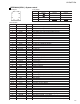

2-14
UX-G6/FS-G6
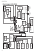
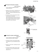
Removing the analog in/digital out board
and the relay board (See Fig.8 to 10)
• Prior to performing the following procedure,
remove the top cover, the rear panel and the
system control board.
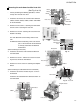
1. Cut the tie band fixing the harness on the side of
the body. Disconnect the harness from connector
CN451 on the analog in/digital out board and
remove the screw G attaching the analog in/
digital out board.
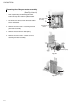
2. Disconnect connector CN455, CN456 and
CN457 on the analog in/digital out board from the
connector on the main & CD servo board.
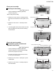
3. Disconnect connector CN443 on the relay board
from the connector on the main & CD servo
board.
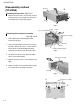
Removing the tuner board (See Fig.11)
• Prior to performing the following procedure,
remove the top cover and the rear panel.
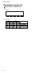
1. Disconnect CN506 on the system control board.
2. Remove the screw H attaching the tuner board.
Fig. 8
Fig. 9
Fig. 10
Fig. 11
CN451
Tie band
Analog in/digital
out board
G
CN451
CN455
CN456
CN457
Analog in/digital
out board
Main & CD servo board
Relay board
Main & CD servo board
CN443
CN506
H
Tuner board
System control board