
Service manual


1-8
UX-G6/FS-G6
3
English
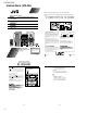
Location of the Buttons and Controls
XT-UXG6
Compact Disc
/Tuner
AX-UXG6
Stereo Amplifier
TD-UXG6
Cassette Deck
Display window
Front Panels
REC
BASS
1
2
34
Become familiar with the buttons and controls on the units.
q
w
e
MI CR O COMPONENT SYSTEM UX-G6
MOS - FET
MOS - FET
OPEN/CLOSE
AUX
VOLUMEMULTI
FM/AM
STANDBY/ON
JOG
1
4
5
6
7
2
3
8
9
p
r
t
y
u
PHONES
1BIT P• E •MD• D• CONVERTER
COMPACT
DIGITAL AUDIO
REC PAUSE
DOLBY B NR
AUTO
REVERSE
REC
i
o
;
a
4
English
Front Panels
AX-UXG6 Stereo Amplifier
1 button and STANDBY/ON lamp (11)*
2 MULTI JOG dial
3 FM/AM button (14)*
4 OPEN/CLOSE button (13)*
5 Display window
6 VOLUME dial (12)
7 AUX button (13, 24)*
XT-UXG6 Compact Disc/Tuner
8 CD tray
9 Remote sensor (5)
p PHONES jack (12)
q 0 (open/close) button for CD tray (16)*
w 6 (play/pause) button (17)*
e 7 (stop) button (17)
TD-UXG6 Cassette Deck
r π (auto-reverse) button and lamp (20, 23)
t DOLBY B NR button and lamp (21, 23)
y REC PAUSE button (22)
u Tape operations indicators (20, 22)
• Tape direction (2 / 3) and REC indicators
i 0 (open/close) button for Tape tray (20)*
o
`
(playback) button (20)*
; 7 (stop) button (21)
a Tape tray
To press the buttons suffixed with * mark also
turns on the system.
Display window
1 Timer mode indicators
•
REC (recording timer) and
DAILY (daily
timer) indicators
2 CD playback mode indicators
• PROGRAM, RANDOM,
(repeat 1),
and
(repeat all) mode indicators
3 FM mode indicators
• STEREO and MONO indicators
4 BASS indicator
Buttons behind the sliding panel
1 DISPLAY/CHARA. button **
2 4 button (14, 17, 18, 21)
3 ¢ button (14, 17, 18, 21)
4 SET button (18, 25)
5 CANCEL button (10, 18, 25)
6 ENTER button **
7 PLAY MODE button (17)
8 REC MODE button (24)
9 TITLE/EDIT button **
p CLOCK/TIMER button (10, 25)
** Used only with MiniDisc recorder XM-G6
(not supplied).
• DO NOT operate any button and control until
the system setup is completed.
• DO NOT operate the sliding panel by hands,
otherwise it will cause serious damages on the
sliding mechanism (see page 13).
M
O
S
-
F
E
T
DISPLAY
/CHARA.
PLAY
MODE
REC
MODE
TITLE
/EDIT
CLOCK
/TIMERCANCEL ENTER
12345 6 7 8 9 p
M
I
C
R
O
C
O
M
P
O
N
E
N
T
S
Y
S
T
E
M
U
X
-
G
6
O
P
E
N
/
C
L
O
S
E
A
U
X
V
O
L
U
M
E
M
U
L
T
I
F
M
/
A
M
STANDBY/ON
J
O
G
SET
SET
4
¢
Continued
5
English
VOLUME
MD
ENTER
AUTO PRESET
PLAY MODE
FM MODE
CANCEL
DISPLAY
/CHARA.
BASS
SLEEP
PANEL
OPEN/CLOSE
REMOTE CONTROL RM-SUXG6E
><
TAPE
FM/AM
DOWN
SET
UP
AUX
2
4
6
;
1
a
s
d
f
g
h
j
k
l
/
3
5
8
p
7
9
w
q
r
e
t
y
i
u
TITTLE/EDIT
REPEAT
TREBLE
DIMMER
CLOCK/TIMER
CD
ACTIVE
BASS EX.
o
Remote Control
When using the remote control, point it at
the remote sensor on the front panel.
Remote Control
1 PANEL OPEN/CLOSE button (13)
2 CLOCK/TIMER button (10, 25)
3 ACTIVE BASS EX. (extension) button (12)
4 TREBLE button (12)
5 BASS button (12)
6 REPEAT button (19)
7 PLAY MODE button (17)
8 TITLE/EDIT button *
9 UP button (12, 14, 17)
p DISPLAY/CHARA. button *
q SET button (18, 25)
w < (left cursor) button (10, 17, 25)
e DOWN button (12, 14, 17)
r MD 6 (play/pause) button *
t FM/AM button (14)
y TAPE
`
(playback) button (20)
u 7 (stop) button (17, 21)
i 4 button (14, 17, 18, 21)
o DIMMER button (10)
;
(standby/on) button (11)
a SLEEP button (28)
s FM MODE button (15)
d AUTO PRESET button (15)
f ENTER button *
g CANCEL button (10, 18, 25)
h > (right cursor) button (10, 17, 25)
j AUX button (13, 24)
k CD 6 (play/pause) button (17)
l ¢ button (14, 17, 18, 21)
/ VOLUME +/– button (12)
* Used only with MiniDisc recorder XM-G6 (not
supplied).
To operate the system correctly using the remote
control
Before using these buttons:
For Tuner operations, press FM/AM button on the
remote control first.
For CD operations, press CD 6 (play/pause)
button on the remote control first.
For Tape operations, press TAPE 23 (playback)
button on the remote control first.
Become familiar with the buttons on the remote control.
Continued
1BIT P•E • MD•D • CONVERTER
PHONES
COMPACT
DIGITAL AUDIO
REC PAUSE
DOLBY B NR
AUTO
REVERSE
REC
MICRO COMPONENT SYSTEM UX-G6
MOS - FET
OPEN/CLOSE
AUX
VOLUMEMULTI
FM/AM
STANDBY/ON
JOG
AUTO PRESET
PLAY MODE
FM MODEBASS
SLEEP
PANEL
OPEN/CLOSE
REMOTE CONTROL RM-SUXG6R
REPEAT
TREBLE
DIMMER
CLOCK/TIMER
ACTIVE
BASS EX.
Remote
Sensor
6
English
Unpacking
After unpacking, check to be sure that you have all the
following items.
The number in the parentheses indicates the quantity of the
pieces supplied.
• AM loop antenna (1)
• FM antenna (1)
• Remote control (1)
• Batteries (2)
• Speaker cords (2)
• External wire (1)
If any is missing, consult your dealer immediately.
Putting the Batteries into the Remote
Control
Insert the batteries — R6P (SUM-3)/AA (15F) — into the
remote control, by matching the polarity (+ and –) on the
batteries with the + and – markings on the battery
compartment.
When the remote control can no longer operate the units,
replace both batteries at the same time.
• DO NOT use an old battery together with a new
one.
• DO NOT use different types of batteries together.
• DO NOT expose batteries to heat or flame.
• DO NOT leave the batteries in the battery
compartment when you are not going to use the
remote control for an extended period of time.
Otherwise, it will be damaged from battery
leakage.
Connecting the System Control Cables and
the External Wire
UX-G6 micro component system consists of three units,
AX-UXG6 Stereo Amplifier, XT-UXG6 Compact Disc/
Tuner, TD-UXG6 Cassette Deck, and SP-UXG6 Speaker
System.
You can easily connect these units using the system control
cables equipped on the rear panel of the units.
• To prevent malfunction, connect the external wire as
illustrated.
DO NOT change vertical stacking order of the
units as illustrated to avoid heat buildup.
• To connect the cables, press the middle of the connector
body until it clicks into the connector on the rear panel.
• To disconnect, if needed, pull the connector out pushing
both sides of the connector body. Never pull out the cables
themselves.
When connecting the system control cables to
the connectors
Make sure to connect the cable to the connector
having the same name such as “FROM
CONNECTOR-A” and “TO CONNECTOR-A.”
Getting Started
To connect
To disconnect
1
2
3
R6P(SUM-3)/AA(15F)
AX-UXG6
TD-UXG6
FROM CONNECTOR-A
TO CONNECTOR-A
FROM CONNECTOR-B
TO CONNECTOR-B
External wire
(supplied)
XT-UXG6
1
2
3
VOLTAGE SELECTOR