
Installation manual


Audio International, Inc. PA-475-A (-B) (-C) Installation
Document #540021, Rev. C, 4/2000 Page 7 of 12
3.3 Cautions and Warnings
3.3.1 It is important to do a pin-to-pin power and ground check on all
connectors. Ensure that power and ground are applied only where
specified. Damage to the unit may result if power or ground is
applied to the wrong points.
3.3.2 DO NOT connect or disconnect the module while power is applied.
3.3.3 DO NOT remove any factory-installed screws. Damage to the units
may result and void any warranties.
3.3.4 ESD (Electro Static Discharge) guidelines shall be followed.
3.4 Wiring Requirements
3.4.1 Introduction
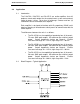
The installing agency shall supply and fabricate all external cables
and mating connectors. The length and routing of external cables
must be carefully studied and planned before attempting installation
of the equipment. Allow adequate space for installation of cable
and connectors. Avoid sharp bends and placing cables near
aircraft control cables. Maintain a minimum clearance of three (3)
inches from any control cable. If wiring is run parallel to
combustible fluid or oxygen lines, maintain a separation of six (6)
inches between the lines.
3.4.2 Power Wires
All power and ground wires shall be 18 AWG (minimum). Power
ground wires shall be grounded within twelve (12) inches of the
unit. All wires shall be in accordance with MIL-W-22759 or
equivalent. Protect power wires with circuit breakers or fuses
located close to the electrical power source bus.
3.4.3 Input Cables
All input cables are 22 AWG (minimum) twisted shielded pair with
the cable shields properly grounded. Twisted shielded cable shall
be in accordance with MIL-W-27500 or equivalent.
3.4.4 Output Cables
All output cables are 20 AWG (minimum), 16 – 18 AWG preferred.
Output cables require twisted, shielded pair with the cable shields
properly grounded. Twisted shielded cable shall be in accordance
with MIL-W-27500 or equivalent.