
Technical information


Application Note: Return Path Troubleshooting
4
• e field unit has a “noise/ingress” feature, which can
be used for troubleshooting. is displays the noise
seen in the headend with optimum resolution of 280
kHz. is simplifies reverse troubleshooting and test-
ing of headend reverse noise or ingress. e newer
headend unit will transmit or broadcast the ingress
from all the return amplifiers connected to it back to
the field unit. is transmits the ingress seen in the
headend on the forward telemetry frequency. So if no
reverse communication is achieved, you will still get a
display of the noise/ingress floor. e noise mode on
the multiple user reverse receiver (Rx) transmits the
total noise in the headend also, but with a resolution
based on the return channel plan resolution.
Note: The newer “Noise” mode can take up to a minute to
track if the reverse is not connected. The new PathTrak
system is faster and more resolution is obtained for
return path monitoring and troubleshooting.
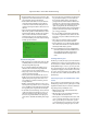
PathTrak
PathTrak is a Return Path Monitoring system that consis-
tently and automatically provides:
• Advanced notice to detect developing problems
• A chance to respond before outages occur, which even-
tually generate into service calls
• Performance archiving
• Ability to organize preventative maintenance
• Reports to correlate RF plant performance to error
reports from modems and telephony systems
Systems can quickly characterize and separate real prob-
lems from insignificant events. This is critical to:
• Perform trend analysis
• Set baseline performance standards
• Certify plant as “ready” for operation
• Document times and frequencies that are more reli-
able, possibly to set times for IPPV downloads and to
do quality of service (QoS) provisioning.
This system can also be incorporated to communicate with
the field units. This allows the field unit to observe noise
and ingress levels in the headend while in the field on a “per
node” basis.
Return Path Egress/Ingress Testing
• e FCC states that the maximum allowable limit for
egress from dc up to 54 MHz is 15 µV/m at 30 meters.
We commonly refer to this as leakage.
• By utilizing forward path egress techniques, it may be
possible to characterize the return path ingress points
to some extent. Testing stringently at 5 or 10 µV/m
everywhere, including the drops, is probably a bet-
ter indication of return path integrity. e hardline
plant only contributes about 5% of the total ingress.
Approximately 75% of ingress is from house and 20%
from the drop.
• Forward path leakage does not necessarily equal in-
gress, though. Some sources of leakage and ingress are
frequency selective. is would lead us to believe that a
reverse frequency would be better to monitor.
• e problem with this is signals on the return path are
only present when communication is taking place.
ey are usually very low in level and bursty in nature.
• We can’t insert a reverse frequency carrier at the head-
end because the diplex filters would block the carrier.
• We can’t insert a carrier at the EOL and look for egress,
because sources of ingress inhibit accurate measure-
ments. Most importantly, the antenna would be huge;
approximately 23.4 feet for 20 MHz! Maybe we can
get away with an octave of that and also tag it with an
identifying signal.
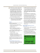
Using a Variable Dwell Time to Catch
Impulse Noise
• Some spectrum analyzers call this sweep speed or the
dwell time. If the sweep speed is too fast, it may skip
over fast impulse noise.
• So we slow down the sweep speed or increase the dwell
time. One problem with a longer dwell time on a spec-
trum analyzer is that it takes longer to scan.
• e nice thing about a longer dwell time is that it’s
easier to catch intermittent signals because it displays
the carrier peak. is is similar to a peak hold every
scan, which makes it great for troubleshooting impulse
noise.
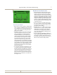
Reverse ingress spectrum trace after 30 s with traditional settings.