
Technical information

Application Note: Return Path Troubleshooting
5
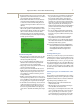
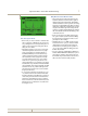
Reverse ingress spectrum trace after 6 s. with dwell-time = 20 ms.
The “Zero Span” Mode
• In this mode, you can view desired-to-undesired ratios
and see peak bursts of TDMA data. You can also mea-
sure peak digital levels, observe high traffic periods &
collisions, and see ingress in the data packet without
taking the service off-line.
• Measuring the Signal-to-Noise (S/N) on return-path
cable modem signals has never been an easy assign-
ment, especially for the novice field technician. A
fundamental difficulty has been the detailed set-up
of the test equipment required to make the modem
S/N measurement. e test equipment is normally
a spectrum analyzer used in a zero-span operating
mode. e zero-span mode requires the user to be
well acquainted with set-up parameters such as trigger
level threshold, sweep time, measurement bandwidth,
video bandwidth, and resolution bandwidth. e field
technician must also be proficient at RF signal evalu-
ation in the time-domain mode, versus the standard
frequency domain mode.
• To overcome the confusing test equipment set-up pro-
cess, JDSU has introduced a new instrument feature
that allows technicians, at all skill levels, to perform ac-
curate return-path cable modem S/N measurements.
e feature is called Modem C/N, and is a standard
feature on all SDA-5000 and SDA-4040D meters with
firmware version 2.2. is feature is accessable under
the Navigator screen.
Why Measure Cable Modem C/N?
• e modem S/N of the return cable plant may well
determine whether the return network is capable of
reliably carrying cable modem traffic. e DOCSIS
standard states that the S/N for upstream (return) digi-
tal signals is 20 dB for QPSK and 25 dB for 16-QAM.
Although most QPSK and 16-QAM signals are robust
enough to transmit through noisier return path envi-
ronments, complying with the DOCSIS S/N standard
will ensure that the cable modem will reliably operate
on the return network.
• Use the pre-amp and low pass filter when doing any
zero-span or modem test. e forward levels hitting
the meter and the test equipment noise floor could
give faulty noise floor readings.
• e RBW is factory set to 2 MHz. To make accurate
measurements in zero-span, you should use a RBW
smaller than the actual payload of the modem. Re-
member there are 5 modem payloads specified. .16,
.32, .64, 1.28, and 2.56 MHz. I’m talking payload not
the filter skirts included.
• You can use the factory default RBW of 2 MHz if you
make the MBW 2 MHz like the RBW, that way no cor-
rection factor is added for carriers that are narrower
than 2 MHz. One problem with this is the noise floor
will be uncorrected when it actually should be.