AVD-K150B/K150E/K150G/ K150N/K150R SERVICE MANUAL AEP Model AVD-K150B/K150E/K150N/K150R UK Model Ver 1.0 2004.06 AVD-K150G AVD-K150B/K150E/K150G/K150N/K150R is the Amplifier, DVD/VIDEO player and tuner section in DAV-D150B/D150E/D150G/D150N/D150R. • Manufactured under license from Dolby Laboratories. "Dolby", "Pro Logic", and the double-D symbol are trademarks of Dolby Laboratories. Confidential unpublished works. Copyright 1992 -1997 Dolby Laboratories. All rights reserved.
AVD-K150B/K150E/K150G/K150N/K150R Laser component in this product is capable of emitting radiation exceeding the limit for Class 1. This appliance is classified as a CLASS 1 LASER product. The CLASS 1 LASER PRODUCT MARKING is located on the rear exterior. CAUTION Use of controls or adjustments or performance of procedures other than those specified herein may result in hazardous radiation exposure. Notes on chip component replacement • Never reuse a disconnected chip component.
AVD-K150B/K150E/K150G/K150N/K150R • SERVICE POSITION-1 (DVD Mechanism Deck) Extension cable (J-2501-242-A, J-2501-245-A) is required to inspect the DVD mechanism deck. DVD mechanism deck J-2501-245-A (1mm/23P/L300) J-2501-242-A (1mm/11P/L300) • SERVICE POSITION-2 (VIDEO Mechanism Deck) Perform the operation check of the VIDEO mechanism deck after the VCR board and the VIDEO mechanism deck are turned upside down.
AVD-K150B/K150E/K150G/K150N/K150R TABLE OF CONTENTS 1. GENERAL ................................................................... 5 2. DISASSEMBLY 2-1. 2-2. 2-3. 2-4. 2-5. 2-6. 2-7. Cover, Front Panel Assembly .......................................... DISPLAY/KEY Board .................................................... Video Mechanism Deck .................................................. DVD Mechanism Deck ................................................... SMPS Board ...........................
AVD-K150B/K150E/K150G/K150N/K150R SECTION 1 This section is extracted GENERAL from instruction manual. Front Panel A VIDEO Ejects the tape in the VIDEO deck. @/1 Switches the DVD/VCR Receiver ON and OFF. VOLUME Adjusts sound level of speakers. AV 3 IN (VIDEO/AUDIO (Left/Right)) Connect the audio/video output of an external source (Audio system, TV/ Monitor, another VCR). Disc Tray (DVD deck) Insert a disc here. INPUT SELECT Selects the VIDEO deck's source (Tuner, AV1, AV2, AV3 OPT or AV3).
AVD-K150B/K150E/K150G/K150N/K150R Display Window SHUFFLE RANDOM playback active SP LP Displays the recording and playback speed. Indicates repeat mode A cassette is in the VIDEO deck. PGM Programmed playback active. BIL Indicates when a BILINGUAL broadcast is being received. STEREO Indicates a stereo broadcast is being received. HI-FI Indicates the unit is playing back a tape recorded in Hi-Fi. ANGLE active OPT Indicates source of DVD/VCR Receiver is DIGITAL AUDIO IN.
AVD-K150B/K150E/K150G/K150N/K150R Remote Control VIDEO Select the output source to VIDEO. DVD Sets the output source to DVD. INPUT SELECT Selects the VIDEO deck's source (AV1, AV2, AV3 OPT, AV3, or Tuner). TUNER FM/AM Selects the DVD/VCR Receiver's tuner as the listening choice. (FM and AM bands) 0-9 numerical buttons Selects numbered options in a menu. TUNING (+/-) To tune in the desired station. MEMORY Memorize a radio station frequency into the tuner. RDS Start a search for a specific PS type.
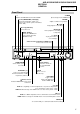
AVD-K150B/K150E/K150G/K150N/K150R Rear Panel FM ANTENNA Connectors Connect the FM antenna to this terminal. SPEAKERS Connectors Connect the six supplied speakers to these terminals. EURO AV2 DECODER/EXTERNAL (VIDEO IN) Connect to Pay-TV decoder, Set Top Box or another video recorder. AC Power Cord Plug into the power source. ANTENNA IN Connect the VHF/UHF/CATV antenna to this terminal. AV3 (OPTICAL IN) (DIGITAL AUDIO IN) Connect to a digital audio output on a digital device.
AVD-K150B/K150E/K150G/K150N/K150R Connections TV and Decoder (or Set Top Box) Connections Make one of the following connections, depending on the capabilities of your existing equipment. SCART INPUT AERIAL Rear of TV Tips • Depending on your TV and other equipment you wish to connect, there are various ways you could connect the DVD/VCR Receiver. Use one of the connections described below.
AVD-K150B/K150E/K150G/K150N/K150R Connections (Continued) Radio Aerial Connections Digital Device Connections Connect the supplied FM/AM antennas for radio listening. the AM loop antenna to the AM antenna 1 Connect connectors. the FM wire antenna to the FM antenna 2 Connect connectors. Connect the OPTICAL IN jacks on the DVD/VCR Receiver to the digital audio out (optical) jacks on your digital device (Game device, Digital Set Top Box, etc.), using optional optical audio cable.
AVD-K150B/K150E/K150G/K150N/K150R Connections (Continued) Speaker System Connections Speaker Positioning Connect the speakers using the supplied speaker cords by matching the colors of the terminals and those of the cords. To obtain the best possible surround sound, adjust the speaker parameters (distance, level, etc.). For a normal setup use 6 speakers (2 front speakers, center speaker, 2 rear speakers and subwoofer).
AVD-K150B/K150E/K150G/K150N/K150R SECTION 2 DISASSEMBLY • This set can be disassembled in the order shown below. • The dotted square with arrow ( ) prompts you to move to the next job when all of the works within the dotted square ( ) are completed. SET 2-1.COVER, FRONT PANEL ASSEMBLY (Page 12) 2-2.DISPLAY/ KEY BOARD (Page 13) 2-3.VIDEO MECHANISM DECK (Page 13) 2-5.SMPS BOARD (Page 14) 2-6.VCR BOARD (Page 15) 2-4.DVD MECHANISM DECK (Page 14) 2-7.
AVD-K150B/K150E/K150G/K150N/K150R 2-2. DISPLAY/KEY BOARD 1 three claws 4 DISPLAY/ KEY board 2 four claws 3 connector (PM602,PM601) 2-3.
AVD-K150B/K150E/K150G/K150N/K150R 2-4. DVD MECHANISM DECK 2 two screws 3 shield cover 1 two screws 5 flexible cable (PMD01) 4 flexible cable (PMD03) 7 DVD mechanism deck 6 door case 2-5.
AVD-K150B/K150E/K150G/K150N/K150R 2-6. VCR BOARD 6 connector (PDV01) 1 four screws q; three screws 4 bracket 7 flexible cable (PVD02) 8 flexible cable (PVD03) 2 connector (PVS01) 5 VCR-DISPLAY pwb holder qs VCR board 9 screw 3 screw qa two claws 2-7.
AVD-K150B/K150E/K150G/K150N/K150R SECTION 3 ELECTRICAL ADJUSTMENTS 3-1. VCR SECTION ELECTRICAL ADJUSTMENT 1. Servo Adjustment 1) PG Adjustment • Test Equipment a) OSCILLOSCOPE b) NTSC MODEL : NTSC SP TEST TAPE • Adjustment And Specification MODE MEASUREMENT POINT ADJUSTMENT POINT SPECIFICATION PLAY V.Out H/SW(W373, W374) R/C TRK JIG KEY 6.5 ± 0.5H • Adjustment Procedure a) Insert the SP Test Tape and play.
AVD-K150B/K150E/K150G/K150N/K150R 3-2. ELECTRICAL TROUBLESHOOTING GUIDE 1. Power (SMPS) CIRCUIT (1) No 5.3VA (SYS/Hi-Fi/TUNER) (2) No 12VA (TO CAP, DRUM MOTOR) NO 5.3VA. NO 12VA. YES Is the F101 normal? YES NO Replace the F101. (Use the same Fuse) YES Is the BD101 normal? Check or Replace the D110. YES NO Replace the BD101. YES Is the R101 normal? Is the Vcc(13V) supplied NO to (+) terminal in D115? Is the Vcc(12V) supplied NO to (-) terminal in D115? Replace the D115.
AVD-K150B/K150E/K150G/K150N/K150R (4) No 5V (TO DVD) (5) No 33V (TUNER) NO 5V. No 33V. YES YES NO Is 5.3VA put into the Q160 Emitter? 5.3VA Line Check. YES Is the Q162 Base “H”? YES NO Check the Power Control. YES Is about 5V put into NO the Q160 Base? YES Check or Replace the Q162/Q160 18 Is Q163 Base “H”? Check or Replace the Q162, R157, R158, R159. Check or Replace Q161, R154, R155. NO Check the Power Control.
AVD-K150B/K150E/K150G/K150N/K150R 2. SYSTEM/KEY CIRCUIT (1) AUTO STOP Auto Stop YES Does the SW25 waveform appear at the IC501 Pin105? NO Check the Drum Motor signal. YES NO Do the T-UP Reel Pulses appear at the IC501 Pin49? YES Do T/UP Reel Pulses appear at the Q514 Base terminal ? YES NO Replace the T/UP Reel Sensor (RS501). Replace the IC501. Does 5.2V appear at the RS501? YES NO Check the Power Circuit.
AVD-K150B/K150E/K150G/K150N/K150R 3. SERVO CIRCUIT (1) Unstable Video in PB MODE Unstable Video in PB Mode. YES Does the Noise level of the screen change periodically? YES Do the CTL pulses appear at the IC501 Pin8? NO Is adjusting the height of the CTL Head accurate? NO YES Does the CFG waveform appear at the IC501 Pin9? YES On tracking do the CTL pulses move? Readjust the height of the CTL Head. NO Replace the IC501.
AVD-K150B/K150E/K150G/K150N/K150R (3) When the Capstan Motor doesn’t run, When the Capstan Motor doesn’t run, Does 12VA appear at the PMC01? NO Refer to “SMPS(CAPSTAN/12Volt) Trouble Shooting”. YES Does 2.8V appear at the PMC01? NO YES Check the PMC01 and the Capstan Motor Ass’y.
AVD-K150B/K150E/K150G/K150N/K150R (4) KEY doesn’t working KEY doesn’t working. Is 5V applied to the IC501 Pin36? NO Refer to “SMPS 5.3VA Trouble Shooting”. NO Replace the defective switches.
AVD-K150B/K150E/K150G/K150N/K150R 4. Y/C CIRCUIT (1) No Video in EE Mode, No Video in EE Mode Does the Video signal appear at the IC301 Pin48? NO Check the 24Pin of Tuner. YES Is 5V applied to the IC301 Pins18, 24, 42, 55, 72, 91? NO Check the 5.2VT, 5.3VA Line.
AVD-K150B/K150E/K150G/K150N/K150R 3. Y/C CIRCUIT (2) When the Y(Luminance) signal doesn’t appear on the screen in PB Mode, Is 5.2VT, 5.3VA applied to the IC301 Pins24, 42, 55, 72, 91? NO Check the line of the 5.2VT, 5.3VA Line. (Power Circuit) YES Is the I2C Bus siganl applied NO to the IC301 Pins68, 69 ? Refer to ‘SYSTEM I2C BUS CHECK Trouble Shooting’. YES Does the normal RF signal appear at the IC301 Pin78? NO Is the V.H.S/W signal applied to the IC301 Pin70? NO Check the System Circuit.
AVD-K150B/K150E/K150G/K150N/K150R 3. Y/C CIRCUIT (3) When the C(Color) signal doesn’t appear on the screen in PB Mode, Is 5.2VT/5.3VA applied to the IC301 Pins24, 42, 55, 72, 91. NO Check the line of the 5.2VT/ 5.3VA Line. (Power Circuit) NO Check the Color Rotary Circuit. (IC501 Pin99 ) NO Check the Color Rotary level. (Check the R303) YES Is the Color Rotary signal applied to the IC301 Pin70? YES Is Color Rotary “H” about 3.
AVD-K150B/K150E/K150G/K150N/K150R 3. Y/C CIRCUIT (4) When the Video signal doesn’t appear on the screen in REC Mode, Is the EE signal normal? NO Check EE Mode. YES Is 5.2VT/5.3VA applied to the IC301 Pins24,42,55,72,91? NO Check the line of the 5.2VT/ 5.3VA Line.(Power Circuit) YES Does PB Mdoe operate normally? NO Check PB Mode.
AVD-K150B/K150E/K150G/K150N/K150R 5. Hi-Fi CIRCUIT (A) No Sound(EE Mode) No Sound. YES Check the TU Audio of IC801 Pins1, 3. NO Check the DVD Audio of IC801 Pins4, 5. NO Check the DVD MODULE. (P8D01 Pins3, 5). Check the AV1 Audio of IC801 Pins6, 7. NO Check the Scart1 Jack. (SC901 Scart1 Audio in Pins2, 6). Check the AV2 Audio of IC801 Pins8, 9. NO Check the AV3 Audio of IC801 Pins10, 11. NO Check the IC751 Pins30, 31. Check the Scart2 Jack. (SC901 Scart2 Audio in Pins2, 6).
AVD-K150B/K150E/K150G/K150N/K150R 3. Y/C CIRCUIT (B) Hi-Fi Playback PB mode YES No Sound. YES Check the Vcc of IC801 (Pins34, 40) YES NO NO Check the Hi-Fi Selection switch. (IC801 Pin41) and the Tape quality. YES Is the RF Envelope at IC801 Pin44 over 2Vp-p? YES NO Check IC801 Pin42(Data), Pin43(Clock) YES NO Check Power 5.2V, 12VT. Check IC501 Pin25 (A.
AVD-K150B/K150E/K150G/K150N/K150R (C) Hi-Fi REC. YES It is impossible to record Hi-Fi Audio signal. YES Check Vcc of IC801.(Pins34, 40) NO Check Power 5V, 12VT. YES Check IC801 Pin42(Data), Pin43(CLOCK). NO Check ports of µ-COM. YES Do Audio signals appear at IC801 Pins16, 17? NO Check Audio input signal of IC801 Pins2, 3(TU.A.), 4, 5(DVD.A.), 6, 7(AVI.A.), 8, 9(AV2.A.), 10, 11(AV3.A.). YES Do FM Audio signals appear at IC801 Pin36? NO Replace IC801.
AVD-K150B/K150E/K150G/K150N/K150R 6. Tuner/IF CIRCUIT (A) No Picture on the TV screen No picture on the TV screen YES Does the Video signal at the TU701 Pin24. NO YES Is +33V applied to TU701 Pin16? NO Check 33V line. YES Is +5V applied to TU701 Pin13? NO Check 5V line. YES Does the Clock signal appear at TU701 Pin11? NO Check the lIC Clock Signal of µ-COM Pin59. NO Check the lIC Data Signal of µ-COM Pin60. YES Does the data signal appear at TU701 Pin12? YES Replace Tuner.
AVD-K150B/K150E/K150G/K150N/K150R (B) No Sound No Sound. YES Check the Vcc of IC751 Pins1, 11, 19, 22, 33. NO Check 5.2V Line. YES Check the Tuner SiF signal at IC751 Pin2. NO Check the Tuner SIF of TU701 Pin22. YES Check the oscillator of IC751 Pins5, 6. NO Replace X751 YES Check the Audio of IC751 Pins30, 31. NO Check the IIC Clock and Data at IC751 Pins12, 13. NO Check the signal flow from IC751 Pins30, 31 to IC801 Pins2, 3. NO Check the IIC Clock and Data at IC801 Pins42, 43.
AVD-K150B/K150E/K150G/K150N/K150R 3-3. DVD & AMP SECTION ELECTRICAL TROUBLESHOOTING GUIDE 1. System operation flow Power On 1. 8032 initializes SERVO, DSP & RISC registers 2. Write RISC code to SDRAM 3. Reset RISC Show LOGO Yes Tray Closed? No Tray Close to Closed position SLED at Inner Side? Yes No SLED Moves to Inner Position 1. Judge whether have disc and disc type 2. Jump to related disc reading procedure Recieve OPEN/ CLOSE Key? No 1. Execute Pressed Key & IR Key 2.
AVD-K150B/K150E/K150G/K150N/K150R 2. T est & debug flow TEST Check the AC Voltage Power PCBA (110V or 220V) No Check the POWER PART Yes Switch on the Power PCBA Is the DC Voltage outputs OK? (5V, 3.3V, 8V, 12V) No Check the POWER PART Yes Is 3.3V and 2.5V DC outputs normal on main PCBA? No Check the regulators or diode(D501). Yes Communication between VCR & DVD is normally? No Check the cable connection. (PDV03) Yes Connect to PC RS232 Cable and update the FLASH memory code.
AVD-K150B/K150E/K150G/K150N/K150R A RESET or Power On. Show LOGO? NO Flash Memory operates properly? NO Check connection lines between FLASH & MT1379 and the FLASH access time whether is sui table or not. NO Check connection lines between SDRAM(IC502,IC503) & MT1379 and the SDRAM is damaged. YES YES SDRAM works properly? YES MT1379 VIDEO outputs properly? NO Check the related circuit of MT1379.
AVD-K150B/K150E/K150G/K150N/K150R B Does the SLED move No to inner side when it is at outer position? Motor Driver STBY Pin is High? No Yes Yes Motor Driver STBY Pin is High? Check the connection line of STBY signal . OK No Check the related circuit of FMSO. No Check the amp circuit on motor driver. Yes SL+ and SL- output properly? Yes Do not put in disc and tray close. Optical Lens has movements for searching Focus? Yes Check the cable connection with MECHA.
AVD-K150B/K150E/K150G/K150N/K150R C Laser turns on when reading disc? No Yes LD01 or LD02 output properly? No Check the laser power circuit on MT1336 and connecting to power transistor. (Q404, Q405) No Check the related circuit on laser power transi stor Yes Collector voltage of power transistor is OK? (Q404, Q405) Yes Check cable connection between transistor output and pick-up head. Disc ID is correct? No Proper RFL signal on MT1336? No Check the related circuit on MT1336 RFL signal .
AVD-K150B/K150E/K150G/K150N/K150R D Yes Focus ON OK? No Proper signals on A, B, C, D of MT1336 No Check connections between MT1336 and pick-up head. No Check the related circuit on MT1336 FEO sugnal . Yes Yes Proper FEO signal on MT1336? Yes Check FEO connection between MT1336 and MT1379 Track On OK? No Proper FEO signal on MT1336? No Check the related circuit on MT1336 Yes Yes Properly TRSO signal on MT1379? No Check the TRSO connection on MT1379 and motor dirver.
AVD-K150B/K150E/K150G/K150N/K150R E Normal Audio output when disc playback? YES NO Audio DAC received correct data stream? NO Check connection between MT1379 & Audio DAC. (Check ARCK, ALRCK ACKL, ASDAT3) NO Check the related circuit of Audio DAC. (Check Audio out Pins 8, 5) YES Normal Audio DAC out? (IC206) YES Check Audio filter, amplify, mute circuit.
AVD-K150B/K150E/K150G/K150N/K150R 3. AUDIO µ -COM Circuit(DVD & AMP) POWER ON Does CD/DVD appear at FLT? NO Does CD/DVD appear at FLT? YES Does Loading appear at FLD? NO Does it appear DVD Error at FLD? NO Check Connector (DVV01) if is normally. Check power part of Main B/D. YES Reconnet it. NO Refer to SMPS. YES NO Check DVD Module. NO YES Check if DVD an Audio Micom Insert is OK. YES NO YES YES Check Power.
AVD-K150B/K150E/K150G/K150N/K150R SECTION 4 MECHANICAL ADJUSTMENTS • Tools and Fixfures for Service SR K 1. Cassette Torque meter SRK-VHT-303(Not SVC part) -V HT -S 2. Alignment tape (See figure below) 3. Torque gauge 600g.Cm ATG 300 250 200 150 0 50 SR VID K CAS EO S TOR ETTE Q MET UE E VHT R -303 -T K- V HT0 SR 50 100 150 200 300 250 4. Torque gauge adaptor 5. Post height adjusting driver 6. + Type driver (φ 5) Parts No.
AVD-K150B/K150E/K150G/K150N/K150R 1. Mechanism Alignment Position Check Purpose:To determine if the Mechanism is in the correct position, when a Tape is ejected. Test Equipment/ Fixture Test Conditions (Mechanism Condition) • Blank tape • Eject Mode (with Cassette ejected) 1) Turn the Power S/W on and eject the Cassette by pressing the Eject Button. 2) Remove the Top Cover and Plate Assembly Top, visually check if the Gear Cam Hole is aligned with the Chassis Hole as below Fig. C-2.
AVD-K150B/K150E/K150G/K150N/K150R cassette without tape. Cover the holes of the End Sensors at the both sides of the Chassis to prevent a light leak. Then the Deck Mechanism drives to the Stop Mode. In this case, the Deck Mechanism can accept inputs of each mode, however the Rewind and Review operation can not be performed for more than a few seconds because the Take-up Reel Table is in the Stop State and can not be detected the Reel Pulses. 2.
AVD-K150B/K150E/K150G/K150N/K150R 4.Guide Roller Height Adjustment Purpose: To regulate the height of the tape so that the bottom of the tape runs along the tape guide line on the Lower Drum. 4-1. Preliminary Adjustment Test Equipment/ Fixture • Post Height Adjusting Driver Test Conditions (Mechanism Condition) • Play or Review Mode Adjustment Procedure Adjustment Point • Guide Roller Height Adjustment screws on the Supply and Take-Up Guide Rollers.
AVD-K150B/K150E/K150G/K150N/K150R 5. Audio/Control (A/C) Head Adjustment Purpose: To insure that the tape passes accurately over the Audio and Control Tracks in exact alignment of the both Record and Playback Modes. 5-1. Preliminary Adjustment (Height and Tilt Adjustment) Perform the Preliminary Adjustment, when there is no Audio Output Signal with the Alignment Tape.
AVD-K150B/K150E/K150G/K150N/K150R 5-2. Confirm that the tape passes smoothly between the Take-up Guide and Pinch Roller(using a mirror or the naked eye). 1) After completing Step 5-1.(Preliminary Adjustment), check that the tape passes around the Take-up Guide and Pinch Roller without folding or curling at the top or bottom. (1) If folding or curling is observed at the bottom of the Take-up Guide then slowly turn the Tilt Adjustment Screw(C) in the clockwise direction.
AVD-K150B/K150E/K150G/K150N/K150R 7. Adjustment after Replacing Drum Assembly (Video Heads) Purpose: To correct for shift in the Roller Guide and X value after replacing the Drum.
AVD-K150B/K150E/K150G/K150N/K150R 1. Check before starting repairs The following faults can be remedied by cleaning and oiling. Check the needed lubrication and the conditions of cleanliness in the unit. Check with the customer to find out how often the unit is used, and then determine that the unit is ready for inspection and maintenance. Check the following parts.
AVD-K150B/K150E/K150G/K150N/K150R 2. Required Maintenance The recording density of a VCR(VCP) is much higher than that of an audio tape recorder. VCR(VCP) components must be very precise, at tolerances of 1/1000mm, to ensure compatibility with the other VCRs. If any of these components are worn or dirty, the symptoms will be the same as if the part is defective. To ensure a good picture, periodic inspection and maintenance, including replacement of worn out parts and lubrication, is necessary.
AVD-K150B/K150E/K150G/K150N/K150R 5-2) Greasing (1) Greasing guidelines Apply grease, with a cleaning patch. Do not use excessive grease. It may come into contact with the tape transport or drive system. Wipe excessive grease and clean with cleaning patch wetted in Isopropyl Alcohol. (2) Periodic greasing Grease specified locations every 5,000 hours.
AVD-K150B/K150E/K150G/K150N/K150R Lever, F/R, Base, Tension GEAR AY, P2 & P3 Lever, F/R Base, Tension Clutch (G-754.
AVD-K150B/K150E/K150G/K150N/K150R SECTION 5 DIAGRAMS • Circuit Boards Location THIS NOTE IS COMMON FOR PRINTED WIRING BOARDS AND SCHEMATIC DIAGRAMS. (In addition to this, the necessary note is printed in each block.) DVD & AMP board For schematic diagrams. Note: • All capacitors are in µF unless otherwise noted. (p: pF) 50 WV or less are not indicated except for electrolytics and tantalums. • All resistors are in Ω and 1/4 W or less unless otherwise specified. • f : internal component.
AVD-K150B/K150E/K150G/K150N/K150R 5-1. BLOCK DIAGRAM – DVD (OVERALL) SECTION – DISC DV33 SPINDLE MOTOR PICK UP M IC5A1 SDRAM DVD:RF0,A,B,C,D CD:RF0,A,B,C,D,E,F MDI1 LD01,LD02, IOA, V2.
AVD-K150B/K150E/K150G/K150N/K150R 5-2. BLOCK DIAGRAM – DVD (AMP) SECTION – 12.
AVD-K150B/K150E/K150G/K150N/K150R VCR DATA OUT DVD CLK DVD VCR DATA IN 5-3. BLOCK DIAGRAM – VCR/PANEL SECTION – DAV LD(+) LD(-) OTPB LED 'H' L/M CONTROL R525, R526 IC501 HD6432197SA SYSTEM CONTROLLER CANAL DET 'H' R/C IN(2W) NC FLDRIVER BUFFER IC601 uPD16315 IC506 MM74HCT244 A.
AVD-K150B/K150E/K150G/K150N/K150R 79 78 76 75 70 68 67 65 V.IN4 FRONT V.IN3 DEC 69 V.OUT MICOM 80 C SYNC 61 CLOCK 63 DATA 65 V.H.SW REC'H' 67 S1 V.OUT 68 S2 V.OUT 69 70 V.OUT (MICOM) C.SYNC 78 CLOCK 79 C.ROTARY DATA (REC MODE) V.H.SW (PB MODE) C.ROTARY 5-4.
AVD-K150B/K150E/K150G/K150N/K150R 5-5. BLOCK DIAGRAM – VCR (TU-VPS) SECTION – 5.4VA VPS V.out 141 875 144 5.2VT S.V.W 94 146 93 59 E d 60 396 (From Power) VPS BLOCK 143 TUIF,NICAM&A2 BLOCK 5.
AVD-K150B/K150E/K150G/K150N/K150R 5-6. BLOCK DIAGRAM – VCR (HI-FI) SECTION – 3 6 AV1 A.IN 'R' K 7 AV2 A.IN 'L' K 10 AV2 A.IN 'R' K 11 IC801 TU V. IN 6 21 NORMAL AUDIO OUT(To AVCP) K NORMAL AUDIO IN(From AVCP) K A.OUT To JACK AV SWITCH VHS HI-FI AUDIO PROCESSOR 22 12 20 24 K K K 26 K IC802 TU A.IN 'L' AV1 A.IN 'L' 16 K 5 A.OUT 'R' K 17 22 TU A.IN 'R' K 10 K DVD A.IN 'R' 4 DVD A.IN 'R' K 29 K DVD A.IN 'L' A.OUT 'L' K 16 28 K d 1 DVD A.IN 'L' Tu A.
AVD-K150B/K150E/K150G/K150N/K150R 5-7. BLOCK DIAGRAM – VCR POWER SECTION – TO SYS FD(+) TO SYS FD(-) TO SYS -29VA Q163 SWITCH FD(+) 15 FD(-) TO TU 33VT PVD01 IC160 8V REG 1 5.3VA 14 2 8V -29VA 13 3 GND GND 12 4 GND 33VA 11 5 3.3V GND 10 6 3.3V 7 5V 8 5V 9 GND 10 3.3V 11 GND 12 GND 13VA IC161 3.3V REG 9 GND 8 3.8VA 7 3.8VA 6 GND 5 5.3VA 4 5.3VA 3 GND 2 GND 1 Q168 SWITCH IC162 3.3V REG Q167 SWITCH TO SYS 5.3VA TO TU/SYS/ Hi-Fi 5.
AVD-K150B/K150E/K150G/K150N/K150R 5-8.
AVD-K150B/K150E/K150G/K150N/K150R 5-9. PRINTED WIRING BOARD – DVD & AMP SECTION (COMPONENT SIDE) – 1 • See page 51 for Circuit Boards Location.
AVD-K150B/K150E/K150G/K150N/K150R 5-10. PRINTED WIRING BOARD – DVD & AMP SECTION (CONDUCTOR SIDE) – 1 • See page 51 for Circuit Boards Location.
AVD-K150B/K150E/K150G/K150N/K150R 5-11.
AVD-K150B/K150E/K150G/K150N/K150R 5-12.
AVD-K150B/K150E/K150G/K150N/K150R 5-13.
AVD-K150B/K150E/K150G/K150N/K150R 5-14.
AVD-K150B/K150E/K150G/K150N/K150R 5-15.
AVD-K150B/K150E/K150G/K150N/K150R 5-16.
AVD-K150B/K150E/K150G/K150N/K150R • VOLTAGE CHART (DVD & AMP BOARD) –1/2 MODE PIN NO. STOP PLAY IC101 1 5.23 MODE PIN NO. STOP PLAY MODE PIN NO. STOP PLAY MODE PIN NO. STOP PLAY MODE PIN NO. STOP PLAY MODE PIN NO. STOP PLAY MODE PIN NO. STOP PLAY MODE PIN NO. STOP PLAY MODE PIN NO. STOP PLAY MODE PIN NO. STOP PLAY 55 2.04 1.96 28 2.47 2.47 38 1.6 1.59 93 0 0 47 0 0 103 2.07 2.18 29 5.15 5.11 47 0.8 1.84 102 0 0 5.22 56 0 0 29 2.47 2.
AVD-K150B/K150E/K150G/K150N/K150R • VOLTAGE CHART (DVD & AMP BOARD) –2/2 MODE PIN NO. STOP MODE PIN NO. STOP MODE PIN NO. STOP MODE PIN NO. STOP 157 0 1.63 212 0 0 22 5.02 5.02 3 15.6 15.6 158 0 3.29 213 0 0 23 3.25 3.24 4 31.59 31.58 159 0 3.27 160 0 1.27 18 0 0.87 24 19 1.98 2.64 25 0 0 5 0 0 3.15 3.15 6 0 161 0 1.27 0 20 2.28 2.18 26 0 3.15 3.15 7 31.59 31.58 162 0 2.35 IC502(SDRAM) 4 163 0 0 1 3.27 3.28 5 0 0 21 2.
AVD-K150B/K150E/K150G/K150N/K150R • See page 51 for Circuit Boards Location. 5-17.
AVD-K150B/K150E/K150G/K150N/K150R 5-18.
AVD-K150B/K150E/K150G/K150N/K150R 5-19.
AVD-K150B/K150E/K150G/K150N/K150R 5-20.
AVD-K150B/K150E/K150G/K150N/K150R 5-21.
AVD-K150B/K150E/K150G/K150N/K150R 5-22.
AVD-K150B/K150E/K150G/K150N/K150R 5-23. SCHEMATIC DIAGRAM – VCR POWER SECTION – [VCR BOARD] (6/6) VCR BOARD (6/6) SWITCH BOARD 12 VCR(1/6) SWITCH BOARD 15 VCR(1/6) SWITCH BOARD 14 VCR(1/6) SWITCH +12V REG IC161 B +3.3V REG +9V REG 12P 2 1 3 G IC160 SMPS BOARD PSV01 4 2 1 3 +8V REG C 4 DVD & AMP BOARD PDV01 2 1 3 4 IC162 +3.3V REG SWITCH SWITCH +5V REG 5.
AVD-K150B/K150E/K150G/K150N/K150R • VOLTAGE CHART (VCR BOARD) Pin No. Voltage IC160 1 12.3 2 8 3 0 4 0 IC161 1 3.8 2 3.3 3 0 4 0 IC162 1 3.8 2 3.3 3 0 4 0 IC201 1 2 2.4 3 3.6 4 5 6 3.7 7 0 8 0 9 10 11 12 1 13 4 14 2.6 15 2 16 3.6 17 4 18 2.2 19 3.6 20 21 0 22 23 4.9 24 4.9 25 2.9 26 2.9 27 3.1 28 0 29 0.7 30 IC301 1 5 2 0 3 2.2 4 0 5 0 6 2.2 Pin No.
AVD-K150B/K150E/K150G/K150N/K150R • See page 51 for Circuit Boards Location. 5-24.
AVD-K150B/K150E/K150G/K150N/K150R 5-25.
AVD-K150B/K150E/K150G/K150N/K150R • See page 51 for Circuit Boards Location. 5-26. PRINTED WIRING BOARD – SMPS SECTION – [SMPS BOARD] 5 1 4 2 IC101 F IC102 3 2 4 1 3 2 4 1 1 3 DVD& BOARD PWS01 IC103 3 1 IC106 IC152 1 4 IC105 5 4 2 1 G IC104 F102 VCR BOARD PVS01 1 2 • Semiconductor Location AVD-K150B/K150E/K150G/K150N/K150R 80 80 Ref. No. BD101 Location F-3 D102 D103 D104 D105 B-5 B-4 F-5 E-5 Ref. No.
AVD-K150B/K150E/K150G/K150N/K150R 5-27. SCHEMATIC DIAGRAM – SMPS SECTION – 330u/450V SMPS BOARD F IC101 DVD& BOARD (3/6) PWS01 1 DEFECTOR 3 30mH KIA431 2 IC102 IC103 PHOTO COUPLER F102 FIXED VOLTAGE ICP-N20 1 PROTECTOR 2 (SD,NK TYPE) 30mH G VCR BOARD (6/6) PVS01 IC104 FS6M07652RTC DEFECTOR T3.
AVD-K150B/K150E/K150G/K150N/K150R • Waveforms – VCR Board – 1 2 IC301 rk, t;, ts, tf, th EE (VIDEO IN) 200 mV/10 msec DIV 5 6 IC301 wa PB (PB RF OUT) IC501
AVD-K150B/K150E/K150G/K150N/K150R SECTION 6 EXPLODED VIEWS NOTE: • -XX and -X mean standardized parts, so they may have some difference from the original one. • Items marked “*” are not stocked since they are seldom required for routine service. Some delay should be anticipated when ordering these items. 6-1. • • The mechanical parts with no reference number in the exploded views are not supplied.
AVD-K150B/K150E/K150G/K150N/K150R 6-2. OVERALL SECTION DVD mechanism deck 56 56 56 55 video mechanism deck not supplied not supplied 58 b c not supplied 57 not supplied 54 59 53 not supplied 56 not supplied not supplied 61 b 52 60 c not supplied not supplied 51 Ref. No. Part No.
AVD-K150B/K150E/K150G/K150N/K150R 6-3. DVD MECHANISM DECK 101 116 113 111 115 101 117 101 109 102 110 117 101 112 101 118 103 117 119 101 117 114 104 not supplied 105 106 not supplied 107 120 108 Ref. No. Part No.
AVD-K150B/K150E/K150G/K150N/K150R 6-4. VIDEO MECHANISM DECK -1 not supplied 159 159 not supplied not supplied 158 157 not supplied not supplied not supplied 156 not supplied 154 not supplied 152 155 not supplied 151 153 Ref. No. 151 152 153 154 155 86 Part No. Description 9-885-034-28 9-885-034-71 9-885-056-15 9-885-034-34 9-885-034-73 OPENER, DOOR GEAR ASSY, RACK (F/L) SPRING, COIL (D35) SPRING, COIL (D35 SWITCH) LEVER ASSY, SWITCH Remark Ref. No. 156 157 158 159 Part No.
AVD-K150B/K150E/K150G/K150N/K150R 6-5. VIDEO MECHANISM DECK -2 202 203 231 204 201 203 205 223 not supplied not supplied 219 222 not supplied 216 not supplied 212 210 218 214 215 224 220 221 225 217 213 211 209 226 227 228 208 229 230 not supplied Ref. No. 206 Part No. Description 201 202 203 204 205 9-885-034-65 9-885-034-44 9-885-034-45 9-885-033-74 9-885-040-03 DRUM ASSY, D35-6CH PAL SCREW, D2.6 L4.5 MSWR3/FZY SCREW, D2.6 L4.
AVD-K150B/K150E/K150G/K150N/K150R 6-6. VIDEO MECHANISM DECK -3 257 258 261 259 260 265 256 255 263 262 266 253 254 264 not supplied 252 251 Ref. No. Part No. Description 251 252 253 254 255 9-885-034-49 9-885-034-10 9-885-034-54 9-885-034-07 9-885-034-09 SCREW, D2.6 L6.8 MSWR3/FZY LEVER, F/R WASHER, STOPPER GEAR, DRIVE BRAKE ASSY, CAPSTAN 256 257 258 9-885-034-08 GEAR, CAM 9-885-034-04 BELT, CAPSTAN 9-885-056-12 MOTOR, CAPSTAN 88 Remark Ref. No. Part No.
AVD-K150B/K150E/K150G/K150N/K150R SECTION 7 ELECTRICAL PARTS LIST DISPLAY DVD & AMP NOTE: • Due to standardization, replacements in the parts list may be different from the parts specified in the diagrams or the components used on the set. • -XX and -X mean standardized parts, so they may have some difference from the original one. • Items marked “*” are not stocked since they are seldom required for routine service. Some delay should be anticipated when ordering these items.
AVD-K150B/K150E/K150G/K150N/K150R DVD & AMP Ref. No. Part No. KEY SMPS VCR Description Remark Ref. No. Part No.
AVD-K150B/K150E/K150G/K150N/K150R VCR Ref. No. Part No. Description Remark < DIODE > D161 D163 D165 D509 D802 6-500-323-01 6-500-323-01 8-719-991-34 8-719-991-34 8-719-991-34 DIODE, RL104 R DIODE, RL104 R DIODE, 1SS133 DIODE, 1SS133 DIODE, 1SS133 < HOLDER > ES501 ES502 9-885-055-78 HOLDER ASSEMBLY 9-885-055-78 HOLDER ASSEMBLY < COIL > FL301 9-885-055-79 COIL, 75M Ref. No. Part No.
AVD-K150B/K150E/K150G/K150N/K150R REVISION HISTORY Clicking the version allows you to jump to the revised page. Also, clicking the version at the upper right on the revised page allows you to jump to the next revised page. Ver. Date 1.0 2004.