
Service manual

16
AVD-K150B/K150E/K150G/K150N/K150R
SECTION 3
ELECTRICAL ADJUSTMENTS
3-1. VCR SECTION ELECTRICAL ADJUSTMENT
1. Servo Adjustment
1) PG Adjustment
• Adjustment And Specification
• Test Equipment
a) OSCILLOSCOPE
b) NTSC MODEL : NTSC SP TEST TAPE
MODE
PLAY
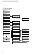
• Adjustment Procedure
a) Insert the SP Test Tape and play.
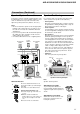
b) Connect the CH1 of the oscilloscope to the H/SW(W373, W374) and CH2 to the Video Out for the VCR.
c) Trigger the mixed Combo Video Signal of CH2 to the CH1 H/SW(W373, W374), and then check the dis-
tance (time difference), which is from the selected A(B) Head point of the H/SW(W373, W374) signal to
the starting point of the vertical synchronized signal, to 6.5H ± 0.5H (412µs, 1H=63µs).
Note - Press FRONT CH UP KEY and FRONT PLAY KEY on Deck playback, and it goes in to ATR PRE-
SET. after the SP Test Tape is inserted.
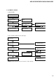
• PG Adjustment Method
a-1) Payback the SP standard tape
b-2) Press the “O” key on the Remote controller and the “PLAY” key on the Front Panel the same time,
then it goes in to Tracking initial mode.
c-3) Repeat the above step(No.b-2), then it finishes the PG adjusting automatically.
d-4) Stop the playback, then it goes out to PG adjusting mode after mony the PG data.
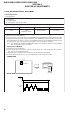
• CONNECTION
•WAVEFORM
V.Out
H/SW(W373, W374)
R/C TRK JIG KEY 6.5 ± 0.5H
MEASUREMENT POINT ADJUSTMENT POINT SPECIFICATION
V.Out
H/SW(W373, W374)
OSCILLOSCOPE
CH1 CH2
V.out
H/SW
R/C KEY
(W373, W374)
H/SW
Composite
VIDEO
6.5H(412µs)