
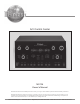
Owner`s manual


5
Important Information
1. The MX136 A/V Control Center has provisions for adding
an optional McIntosh TM1 AM/FM Tuner Module for Radio
Station Reception. The TM1 is available from your McIntosh
Dealer and can be installed at any time, usually while you
wait. Refer to page 52 for additional TM1 information.
2. Before making any connections to the MX136, make sure the
Main POWER Switch is in the Off position. Failure to do so
could result in malfunctioning of some or all of the system’s
normal operations.
3. Zone A accepts, unbalanced Analog Signals, Balanced
Analog Audio Signals and Digital Audio Signals. Zone B
and the Record Output Signal only accept unbalanced
Analog Signals. When connecting source devices with audio
ouputs to the MX136, make sure to also connect the
unbalanced outputs.
4. The connection of a turntable to the PH/AUX Input jacks
requires changes to be made in the SETUP Mode, refer to
page 32. If a recording is made from the turntable and/or
listening to a record in Zone B of the MX136, both the
INPUT A and INPUT B Controls need to be placed in the
PH/AUX position.
5. Connecting Cables are available from the McIntosh Parts
Department:
Data and Power Control Cable Part No. 170-202
Six foot, shielded 2 conductor, with 1/8 inch stereo
mini phone plugs on each end.
Control Center to Multi-Channel Power Amplifier
Cable Part No. 170-631
Six foot, DB25, shielded, straight through, 25
conductor male-to-female cable.
6. When the MX136 is connected to some McIntosh
Multichannel Power Amplifiers with a 25 conductor cable,
the amplifier meters may automatically indicate the output
of individual channels during the Speaker Level Setup
Operation. Refer to the Power Amplifiers Owner’s Manual
for additional information.
7. The MX136 Input Source Name “DVD” is equivalent to “V-
Aux” on some McIntosh Keypads, Remote Controls and
Audio/Video Control Centers.
8. Up to two McIntosh Sensors or Keypads can be wired in
parallel for both Zones A and B.
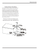
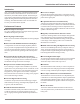
9. When a McIntosh WK-2 Keypad or a R649 Sensor is to be
connected to the McIntosh MX136 A/V Control Center that
uses a RJ-45 Connector Plug instead of the “F” Coaxial
Connector, connect the Center Conductor to Pin 1 and the
Shield Conductor to Pin 2. Refer to the figure below.
Important Information
10. The Zone A and Zone B IR Inputs, with 1/8 inch mini phone
jacks, are configured for non-McIntosh IR sensors such as a
Xantech Model 291-80. To avoid possible interaction,
disable the MX136 Front Panel Sensor with the switch
recessed in the bottom panel behind and to the left of the
Sensor.
11. System Setup operations must be performed in the order
they appear in the Main System Setup Menu as they are
interactive.
12. In order to hear bass frequencies below 80Hz, your system
must include either a Subwoofer or Large Front
Loudspeakers.
13. When an assigned Digital Input and a matching Analog
Input are in use, the MX136 automatically searches first for
a Digital Signal. If no Digital Signal is sensed, it switches to
the Analog Input.
14. Some disk players have the ability to provide only a single
output (Digital or Analog) when a DTS Sound Track is
playing. If the Digital Output is selected in the player setup
mode, the players Analog Audio Output Signal will have the
undecoded DTS Sound Signal which will be heard as noise.
15. There are three types of Video Signals that can be
connected to and selected by the MX136; Composite, S-
Video and Component. Zone A and B, VCR 1 and 2 have
both Composite and S-Video Outputs; the Component Video
Output is for Zone A only. The MX136 has Digital Video
Processing Circuitry that will Up-Convert the desired
Composite Input to S-Video; it will also Up-Convert the
desired Composite and/or S-Video Inputs to Component
Video.
16. The MX136 has built-in HDMI Digital Video Selection for
Zone A and has Digital Video Processing Circuitry to
convert and upscale any Composite Video, S-Video, and
Component Video Signals to Digital Video (480p, 720p or
1080i).
17. To view Component Video, S-Video and Composite Video
Input Sources through the HDMI Video Monitor A Output, it
is necessary to first go into the Setup Mode, select the Input
Setup Menu (HMDI Video/Component Video Menu items)
and make the appropriate changes from the default settings.
For additional information refer to pages 35, 36 and 37.
18. For additional connection information, refer to the owner’s
manual(s) for any component(s) connected to the MX136
A/V Control Center.
RJ-45
Plug
Data Ground
(to Pin 2)
Shielded Cable Data Signal
(to Pin 1)
“F” Connector
Pin 1 Pin 8