
Owner`s manual


!
8!
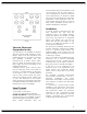
Output Tube Bias Adjustment
As shipped from the factory, the output
‘bias’ adjustments are set for a nominal
65mA per KT120 tube. Under these idle
conditions the tubes are each
dissipating approximately 27 watts of
their 60 watt rating. This point of
operation provides ‘enriched’ Class AB1,
and will satisfy the most critical listener.
For best results, operate and adjust the
Reference150 at 120VAC. Adjustment
must be made under zero-signal
conditions after at least 15-20 minutes of
uninterrupted stabilization time.
A digital voltmeter capable of accurate
measurements with 0.lmVDC resolution is
preferred for accurate adjustment (must
have 31/2 digit display). Use the plastic
alignment tool provided to make the
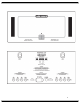
adjustment. The measurement points are
yellow and black banana test jacks next
to each output tube. Adjust the ‘bias’
for a voltage reading of 65mVDC (.065
Volt DC) at the blue bias pot for one of
each output tube pair as follows, noting
the voltage setting of the larger V
number tube in each pair is slaved to
the adjustment setting of its lower V
number companion tube: Adjust V5 for
65mVDC and measure its companion
tube V7 to verify a reading of 57 to
73mVDC. Repeat procedure by
adjusting and measuring V9 to read
65mVDC and verify V11 reads 57-
73mVDC; adjust and measure V6 to
read 65mVDC and verify V8 reads 57-
73mVDC, and finally adjust and measure
V10 to read 65mVDC and verify that V12
reads 57-73 mVDC.
Cooling Fan Speed
Adjustment
The two D.C. cooling fans located at the
rear of the Reference 150 are adjustable
in speed. Locate the red colored
dipswitch under the top cover at the top
near the center of the back panel. For
highest fan speed move both white tabs
on the red dip switch to the upward
position; for medium fan speed move
either one of the tabs to the downward
position, and for low fan speed move
both tabs to the downward position. For
maximum cooling and extended tube
life, use the highest fan speed possible.
Be sure to first turn off and unplug the
Reference 150 from its power
receptacle before unscrewing the top
cover to access the switch. Refasten the
top cover before resuming operation.
Do not operate the Reference 150 with
fans disconnected or if one or both fans
should stop running.
Hour Meter
An LCD hour meter of elapsed tube
operating time can be viewed through
the top cover near the front, mounted
on the right main circuit board. This
displays accumulated hours of vacuum
tube service life. If the amplifier is
unplugged from A.C. supply, total
accumulated hours are retained. May
be reset by qualified technician.
Contact Audio Research Customer
Service for more information about reset
procedure.
Servicing
Because of its careful design and
exacting standards of manufacture,
your Reference 150 amplifier should
normally require only minimal service to
maintain its high level of performance.
Caution: The Reference 150 amplifier
contains sufficient levels of voltage and
current to be lethal. Do not tamper with
a component or part inside the unit.
Even with the power turned off, a
charge remains in the energy storage
capacitors for some time. Refer any
needed service to your authorized
Audio Research dealer or other qualified
technician. Additional questions
regarding the operation, maintenance
or servicing of your amplifier may be
referred to the Customer Service
Department of Audio Research
Corporation at 763.577.9700 (CST). When
ordering a service manual from Audio
Research or an authorized dealer, be
sure to identify the serial number on your
amplifier.