
Product manual


AEWCI Software Manual
10
1
2
3
4
5
6
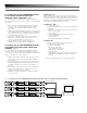
Fig. G Channel Detail window.
Navigating the Software
Main System window (Figure F)
The Main System window shows all of the active (enabled) receiver
channels on the network. A vertical channel “strip” represents each
channel. The window can be resized to view more channel strips.
Alternate views (medium and small) can be selected by clicking the
View menu.
The following is displayed for each channel strip:
• RF level and which True Diversity Tuner is active
• AF (Audio) level and audio overload peak indicator
• Battery Fuel Remaining and Low Battery Condition
• TX and RX Mute status
• Channel Frequency and name
(Selectable TX or RX name per channel)
Double clicking any channel strip opens a “Channel Detail Window”
with additional channel information and user adjustable parameters.
Channel Detail window (Figure G)
SECTION 1: Monitor RF levels for each antenna. The red indicators
at top show which True Diversity tuner is selected (which antenna
is receiving the stronger signal). RF levels are grayed out for AEW-
R4100 units and for AEW-R5200 units linked via link cables, because
link cables do not transmit RF-level data.
SECTION 2: Monitor AF level. The red indicator at top lights when
AF level reaches +12 dB (peak audio level). AF level is grayed out
for AEW-R4100 units and for AEW-R5200 units linked via link cables,
because link cables do not transmit AF-level data.
SECTION 3: Monitor and control the following receiver functions (see
Page 11 for instructions on editing settings):
• Receiver name
• Frequency
• Squelch level
• Display in Main System window channel strip (transmitter
name or receiver name)
• Receiver lock status
SECTION 4: Monitor and/or control the following receiver features:
• Monitor the status of, and enable or disable, Meter Hold and
Antenna Power (clicking the Off button beside each function
toggles it On)
• Monitor the receiver’s IP address and link address (master
or slave)
• Mute the receiver by clicking on the Rx Mute button (shows up
red when system is muted) and monitor the status of the
transmitter (system’s failure to unmute when Mute button is
clicked may indicate a transmitter problem)
• Close the window using the Close button
SECTION 5: Monitor the following transmitter features:
• Transmitter name
• Transmitter type
• Input type (if handheld, whether condenser or dynamic; (if
UniPak
®
, whether mic or instrument)
• Trim setting
• Power level (high or low)
• Transmitter lock status
SECTION 6: Monitor transmitter battery level and mute status. If the
battery level falls below 1/4 power, the Low Batt indicator will light
in red.
Note: The low battery indicator on the transmitter and receiver LCDs
does not display until all indicator bars are gone.
Fig. F Main System window