
User Manual


System 10 Installation and Operation
3
Each System 10 professional digital wireless system includes a
receiver and either a body-pack transmitter or a handheld microphone/
transmitter. ATW-1101 UniPak
®
body-pack transmitter systems include
models pre-packaged with either an AT-GcW guitar cable (/G), a
PRO 8HEcW headworn microphone (/H), a PRO 92cW headworn
microphone (/H92), a PRO 92cW-TH headworn microphone (/H92-
TH), or an MT830cW lavalier mic (/L) for particular applications. All A-T
Wireless Essentials
®
microphones and cables, available separately, are
pre-terminated for use with any ATW-1101 system.
Because System 10 packaging is designed to hold all versions
of the system, some compartments in the carton may be intentionally
left empty.
The ATW-R1100 receiver includes a switching power supply that
automatically adapts to changes in mains voltage.
The versatile ATW-T1001 UniPak
®
body-pack transmitter has both
a high-impedance input for instruments, and a low-impedance input
with bias connection for use with dynamic and electret condenser
microphones. The ATW-T1002 handheld transmitter features a
unidirectional dynamic microphone element.
Both the body-pack and handheld transmitters use internal AA batteries
and have Power/Mute switches and input Trim (level) adjustments.
Receiver Installation
Location
For best operation the receiver should be at least 3' (1 m) above the
ground and at least 3' (1 m) away from a wall or metal surface to
sources such as other digital equipment, microwave ovens, as well as
VOLUME UNBALANCED
BALANCED
DC 12V IN
500mA
MIN. MAX.
1 1
2
4 6
3 5
1 2 3 4 5
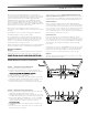
away from large metal objects. Keep System 10 receiver 30' (9 m)
away from wireless access points. In multi-channel systems, position
receivers at least 3' (1 m) apart and keep operating transmitters at least
6' (2 m) from the receivers to help assure maximum RF performance.
Output Connection
There are two audio outputs on the back panel: balanced XLR-type
output and unbalanced ¼" TRS phone jack. Use shielded audio cable for
the connection between the receiver and the mixer. If the input of the
mixer is a ¼" jack, connect a cable from the ¼" unbalanced audio output
on the back of the receiver housing to the mixer. If the input of the
mixer is an XLR-type input, connect a cable from the balanced XLR-type
audio output on the back panel to the mixer.
Power Connection
Connect the DC plug on the included AC power adapter to the DC
power input on the back of the receiver. Secure the cord over the cord
hook on the back of the receiver, to keep the plug from being detached
by an accidental tug on the cord. Then plug the adapter into a standard
120 Volt 60 Hz or 230 Volt 50 Hz (depending on global location) AC
power outlet.
(Note that the receiver has no power Off/On switch. The receiver will be
energized whenever the power adapter is connected and plugged into
the AC outlet. Unplug the power supply from the AC outlet when the
system is not in use — both for safety, and to conserve energy.)
Antennas
Rotate the permanently attached antennas in the shape of a “V” (both
45° from vertical) for best reception.
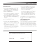
ATW-R1100 Receiver Controls and Functions
Figure A — Front Panel Controls and Functions
1. Antennas: Position the antennas as shown.
2. System ID Select Switch: Press to cycle through System ID
numbers. (System ID is an identical number assigned to a paired
3. System ID Display: Shows System ID number.
4. Pairing Switch: Press to initiate pairing.
5. AF Peak Indicator: Only lights when audio distortion is present at
maximum modulaton. Not affected by position of Volume control.
6. Pair Indicator: Glows green to indicate presence of paired
transmitter. Also blinks green to indicate pairing mode activated.
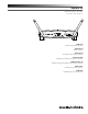
Figure B — Rear Panel Controls and Functions
1. AF Level (Volume) Control: Adjusts audio output level of both AF
Output jacks; maximum output is fully clockwise.
2. Unbalanced Audio Output Jack: ¼" phone jack. Can be connected to
an unbalanced aux-level input of a mixer, guitar amp or tape recorder.
3. Balanced Audio Output Jack: XLRM-type connector. A standard
2-conductor shielded cable can be used to connect the receiver
output to a balanced microphone-level input on a mixer or
4. Power Input Jack: Connect the DC plug from the included in-line
AC adapter.
5. Cord Hook: Loop the cord around the cord hook to keep the DC
plug from pulling out accidentally.