System 10 PRO Digital Wireless System Installation and Operation ATW-1301 UniPak® Transmitter System ATW-1301/L Lavalier Microphone System ATW-1302 Handheld Microphone System ATW-1311 Dual UniPak® Transmitter System ATW-1311/L Dual Lavalier Microphone System ATW-1312 UniPak®/Handheld Combo System ATW-1312/L Lavalier/Handheld Combo System ATW-1322 Dual Handheld Microphone System
System 10 PRO Installation and Operation CAUTION RISK OF ELECTRIC SHOCK DO NOT OPEN WARNING: TO REDUCE THE RISK OF FIRE OR ELECTRIC SHOCK, DO NOT REMOVE SCREWS. NO USER-SERVICEABLE PARTS INSIDE.REFER SERVICING TO QUALIFIED SERVICE PERSONNEL. WARNING: TO REDUCE THE RISK OF FIRE OR ELECTRIC SHOCK, DO NOT EXPOSE THE APPLIANCE TO RAIN OR MOISTURE. CERTIFICATION: THIS DEVICE COMPLIES WITH PART 15 OF THE FCC RULES. THIS DEVICE COMPLIES WITH INDUSTRY CANADA LICENSE-EXEMPT RSS STANDARD(S).
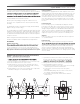
System 10 PRO Installation and Operation one or two receiver units that may be docked in the chassis or mounted remotely, and one or two transmitters of either the handheld also include one or two lavalier mics that attach to the body-pack included RJ12 cable to allow for simultaneous use of all receivers and increased stability of the multi-channel system. Because System 10 packaging is designed to hold all versions of the system, some compartments in the carton may be intentionally left empty.
System 10 PRO Installation and Operation Figure B, C & D — Rear Panel Controls and Functions 1. RJ45 Connector: Use Ethernet cable (not included) to mount receiver remotely up to 328' (100 m) from chassis. 2. AF Level (Volume) Control: Adjusts audio output level of both AF output jacks; maximum output is fully clockwise. 3. Ground Lift Switch: Disconnects the ground pin of the balanced output jack (5) from ground. Normally, the switch should be to the left (ground connected).
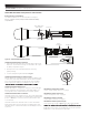
System 10 PRO Installation and Operation ATW-RU13 Receiver Unit Controls and Functions Figure E — ATW-RU13 Functions 1. Antenna: Attach antennas and angle them away from each other so a “V” shape is formed. Antennas attach via SMA connectors. 2. Mounting Socket: ¼"-20 thread socket for mounting receiver remotely to tripod or other device with a ¼" screw. 3.
System 10 PRO Installation and Operation ATW-T1002 Transmitter Setup Controls and Functions Battery Selection and Installation Two alkaline AA batteries are recommended. When inserting the batteries, observe correct polarity as marked inside the battery compartment. Power / Battery / Mute Status Indicator Level Control System ID Display Pairing Switch Battery Compartment Screwdriver Figure H — ATW-T1002 Handheld Transmitter Handheld Transmitter Battery Installation 1.
System 10 PRO Installation and Operation Microphone / Instrument Level Control Pairing Switch Screwdriver System ID Display Battery Compartment Figure I — ATW-T1001 UniPak® Transmitter UniPak® Transmitter Battery Installation 1. Slide off the battery cover. 2. Carefully insert two fresh AA alkaline batteries, observing polarity markings. 3. Replace the battery cover (Fig. I).
System 10 PRO Installation and Operation System Operation CAUTION! The small trimmer controls are delicate; use only the supplied screwdriver. Do not force the trimmers beyond their normal 190° range of rotation. level before starting up the wireless system. Do not switch on the transmitter yet. Setting System ID Number & Pairing your Transmitter and Receiver Receiver on... Plug the power supply into an AC power source, then turn on the power switch. The blue System ID Display will illuminate.
System 10 PRO Installation and Operation Clearing Individual ID Pairings 1. Press the receiver’s System ID button to select the ID number you wish to clear. The number will begin to blink. 2. Press and hold the Pair button and, while continuing to hold it, press and hold the ID button until the display shows a blinking “o.” This indicates that your selected ID number has been cleared. 3.
System 10 PRO Installation and Operation OVERALL SYSTEM Operating Frequencies Dynamic Range Total Harmonic Distortion Operating Range 2.4 GHz ISM band (2400 to 2483.5 MHz) >109 dB (A-weighted), typical <0.
System 10 PRO Installation and Operation This page intentionally left blank.
System 10 PRO Installation and Operation Audio-Technica Corporation audio-technica.