
User Manual


System 10 PRO Installation and Operation
4
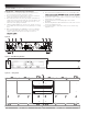
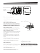
Figure B, C & D — Rear Panel Controls and Functions
1. RJ45 Connector: Use Ethernet cable (not included) to mount
receiver remotely up to 328' (100 m) from chassis.
2. AF Level (Volume) Control: Adjusts audio output level of both AF
output jacks; maximum output is fully clockwise.
3. Ground Lift Switch: Disconnects the ground pin of the balanced
output jack (5) from ground. Normally, the switch should be to the
left (ground connected). If hum caused by a ground loop occurs,
slide switch to the right (ground lifted).
4. Unbalanced Audio Output Jack: ¼" phone jack. Can be connected
to an unbalanced aux-level input of a mixer, guitar amp or recording
device.
5. Balanced Audio Output Jack: XLRM-type connector. A standard
2-conductor shielded cable can be used to connect the receiver
output to a balanced microphone-level input on a mixer or
6. Receiver Chassis Link IN/OUT Connector: Use included RJ12 cable
receivers) may be linked.
7. Cord Hook: Loop the cord around the cord hook to keep the DC plug
from pulling loose accidentally.
8. Power Input Jack: Connect the DC plug from the included
AC adapter.
9. Rack Mounting Brackets: Attach brackets to the sides of the receiver
chassis using supplied screws.
10. Joining Plate: Attach to the bottom of two receiver chassis using
supplied screws.
Figure C — Rack Mounting Brackets
Figure B
3
6 7 8421
9
5
Figure D — Joining Plate
10