
User Manual
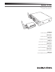


System 10 PRO Installation and Operation
3
one or two receiver units that may be docked in the chassis or
mounted remotely, and one or two transmitters of either the handheld
also include one or two lavalier mics that attach to the body-pack
included RJ12 cable to allow for simultaneous use of all receivers and
increased stability of the multi-channel system.
Because System 10 packaging is designed to hold all versions of
the system, some compartments in the carton may be intentionally
left empty.
The ATW-R1300 includes a switching power supply that automatically
adapts to changes in mains voltage.
The versatile ATW-T1001 UniPak
®
body-pack transmitter has both a high-
impedance input for instruments, and a low-impedance input with bias
connection for use with dynamic and electret condenser microphones.
The ATW-T1002 handheld transmitter features a unidirectional dynamic
microphone element.
Both the body-pack and handheld transmitters use internal AA batteries
and have Power/Mute switches and input Trim (level) adjustments.
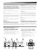
Installation
Receiver Unit Location
sight of transmitter and away from any large obstructions. Keep the
receiver unit away from noise sources such as other digital wireless
equipment, microwave ovens, as well as away from large metal objects.
Keep System 10 receivers 30' (9 m) away from wireless access points.
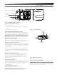
Output Connection
The ATW-R1300 is equipped with two audio outputs for each receiver:
a balanced XLR-type output and an unbalanced ¼" TRS phone jack. Use
shielded audio cable for the connection between the receiver and the
mixer. If the input of the mixer is a ¼" jack, connect a cable from the
¼" unbalanced audio output on the back of the receiver chassis to the
mixer. If the input of the mixer is an XLR-type input, connect a cable
from the balanced XLR-type audio output on the back of the chassis to
the mixer.
Power Connection
Connect the DC plug on the included AC power adapter to the DC
power input on the back of the receiver chassis. Secure the cord over
the cord hook on the chassis to keep the plug from being accidentally
dislodged. Plug the adapter into a standard 120 Volt 60 Hz AC power
outlet. The receiver chassis is equipped with a power On/Off switch.
Turn the power off when system is not in use, and unplug the power
supply if you expect not to use the system for an extended period.
Antennas
For best reception, position the removable antennas in the shape of a
“V” so that both tilt 45°.
Link Connection
When using multiple systems together it is strongly recommended
with each system. (Linking is not necessary if you are using only a
single chassis.) Linking creates a much more stable environment in
which receivers work together, with all receiving, transmitting and
frequency allocation coordinated to prevent audio dropouts and enable
simultaneous use of up to 10 channels. See “Linking Systems” on page
9 for more details.
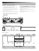
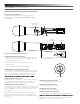
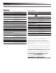
ATW-RC13 Receiver Chassis Controls and Functions
Figure A — Front Panel Controls and Functions
1. Power Switch: Press to turn power on and off.
2.
service technician.
3. Receiver Unit Docks: Insert individual receivers to use them locally.
4. Receiver Unit Releases: Press to eject receivers.
5. Audio Indicator (one for each receiver): Illuminates green when
sound is received from transmitter, yellow when audio is nearing
peak level, and red when peak level is reached.
6. Pairing Indicator (one for each receiver): Flashes green in pair mode;
illuminates solidly green once transmitter is paired.
Figure A
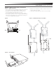
7. System ID Select Switch (one for each receiver): Press to cycle
through System ID numbers. (System ID is a shared number
purposes.)
8. Pairing Switch (one for each receiver): Press to initiate pairing.
9. System ID Display includes the following:
a. RF Signal Level Indicator (one for each receiver): Shows strength
of the RF signal received from the transmitter
b. System ID (one for each receiver): Shows the System
ID number
c. Transmitter Battery Gauge TX (one for each receiver): Shows
the capacity of the transmitter’s batteries
d. Link Indicator: Shows that the chassis has been linked to
another chassis
2
931
4
5
6 7 8
d
b
c
a