
User Manual


System 10 PRO Installation and Operation
5
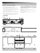
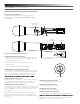
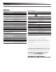
ATW-RU13 Receiver Unit Controls and Functions
Figure E — ATW-RU13 Functions
1. Antenna: Attach antennas and angle them away from each other so
a “V” shape is formed. Antennas attach via SMA connectors.
2. Mounting Socket: ¼"-20 thread socket for mounting receiver
remotely to tripod or other device with a ¼" screw.
3. Receiver Status Indicator: LED is off when receiver is without
power, blinks slowly when receiver is not paired with a transmitter,
blinks quickly during pairing process, and illuminates solidly green
once receiver is paired with a transmitter.
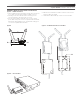
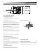
Figure E Figure F — AT8690 RU13 Holder Front and Back
2
1
3
4
5
4. RJ45 Connector: Run Ethernet cable to chassis to mount receiver
remotely (cable not included).
5. Holder Release Tab: Lift tab up to release receiver from holder.
Figure G — RU13 and RC13