2000 Series Frequency-agile True Diversity UHF Wireless System Installation and Operation
2000 Series Installation and Operation This device complies with part 15 of the FCC Rules. Operation is subject to the condition that this device does not cause harmful interference. This device complies with INDUSTRY CANADA R.S.S. 210, en conformité avec IC: RSS-210/CNR210. Operation is subject to the following conditions: 1) This device may not cause harmful interference and 2) this device must accept any interference received, including interference which may cause undesired operation.
2000 Series Installation and Operation Switchable antenna power is also provided. Soft-touch controls provide convenient access to selection of operating frequency and automatic scanning, while an LCD information display provides constant monitoring of system operation. The receiver is half-width for a standard 1U 19" rack mount; rack-mount adapters are included. Two receivers can be mounted side by side, using an optional AT8630 joining-plate kit.
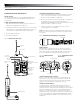
2000 Series Installation and Operation Receiver Controls and Functions Fig. B – Front Panel Controls and Functions 1 2 3 4 1. POWER SWITCH: Press the Power switch in to turn the receiver on. The LCD window will light, and the operating channel number will be displayed in the window. To turn the receiver off, press the Power switch again. 5 Fig. C – Receiver LCD Window Display 2. LCD WINDOW: Liquid Crystal Display indicates channel setting and operational readings. See Fig. C for examples. 3.
2000 Series Installation and Operation Fig. D – Rear Panel Controls and Functions 15 12V 60mA 10 10. ANTENNA INPUT JACK: BNC-type antenna connector for Tuner “B.” Attach the antenna directly, or extend it with a low-loss antenna cable. See the “Antennas” section on page 3 for more details. 11. ANTENNA POWER SWITCH: Two-position switch turns on/off the 12V DC antenna power for use with powered antennas or accessories. Factory setting is off. See the “Antennas” section on page 3 for more details.
2000 Series Installation and Operation Transmitter Controls and Functions Battery Selection Two 1.5V AA alkaline batteries or rechargeable AA NiMH batteries for use with Audio-Technica’s ATW-CHG2 Recharging Station are recommended. UniPak® Transmitter Battery Installation 1. Open the transmitter door by pressing gently on the side-cover indentations and pulling back the hinged cover. 2. Lift the battery-keeper arm, and carefully insert two fresh 1.
2000 Series Installation and Operation System Operation Switch on the receiver. Do not switch on the transmitter yet. Receiver On… The LCD display will light up. If two or more of the RF LCD segments light up at this point, there may be RF interference in the area. If this occurs, change operating channels (select another frequency). How to Make Operating Channel Changes Operating channel changes (frequency changes) may be made in two ways: manually and automatically. To change channel manually 1.
2000 Series Installation and Operation Setting Levels (Continued) ATW-T210a UniPak® Transmitter Trimmer adjustments in the UniPak® transmitter (Fig. E ) will enable you to use microphones or instruments with different output levels. Fig. E – UniPak® Transmitter Open 1. For MIC: Set microphone level trim control fully clockwise (maximum) and instrument level trim control fully counterclockwise (minimum). Factory setting is fully clockwise (maximum).
2000 Series Installation and Operation Specifications† Overall System UHF Operating Frequencies Frequency Range Band D: 656.125 to 678.500 MHz Band E: 795.500 to 805.875 MHz Band F: 854.900 to 864.900 MHz Band G: 722.125 to 744.500 MHz Band I: 487.125 to 506.500 MHz Band U (A): 606.500 to 613.300 MHz Band U (B): 614.300 to 629.900 MHz Number of Channels 10 10 10 10 10 10 10 Not all frequencies are available in all areas. Please check with local regulations.
2000 Series Installation and Operation 2000 Series Frequency Channel Plan Band D Channel 1 2 3 4 5 6 7 8 9 10 Frequency-MHz 656 . 125 659 . 375 660 . 000 662 . 125 665 . 125 669 . 750 671 . 500 677 . 000 678 . 125 678 . 500 Band E Channel 1 2 3 4 5 6 7 8 9 10 Frequency-MHz 795.500 795.825 797.825 798.675 800.400 800.975 803.850 804.400 804.700 805.875 Band F Channel 1 2 3 4 5 6 7 8 9 10 Frequency-MHz 863 . 100 863 . 500 864 . 100 864 . 900 854 . 900 855 . 275 855 . 900 856 . 175 858 . 200 861 .
Statement of Compliance The ATW-T210a, ATW-T220a and ATW-R2100b are intended to use in BG, CZ, DE, DK, EE, ES, FI, FR, GB, GR, HR, HU, IE, IT, LT, LV, MT, NL, PL, PT, RO, SE, SI and SK. Please note: Frequency usage is different for each country. Your Audio-Technica agent will have all the necessary details on the available legal frequencies for your area. Statement of Compliance BG CZ DE DK EE ES FI FR GB GR HR HU IE IT LT LV MT NL PL PT RO SE SI SK С настоящото, Audio-technica Corp.
To reduce the environmental impact of a multi-language printed document, product information is available online at www.audio-technica.com in a selection of languages. Per evitare l’impatto ambientale che la stampa di questo documento determinerebbe, le informazioni sui prodotti sono disponibili online in diverse lingue sul sito www.audio-technica.com.