
User's Manual


2000 Series Installation and Operation
3
Switchable antenna power is also provided. Soft-touch controls provide
convenient access to selection of operating frequency and automatic
scanning, while an LCD information display provides constant
monitoring of system operation. The receiver is half-width for a standard
1U 19" rack mount; rack-mount adapters are included. Two receivers can
be mounted side by side, using an optional AT8630 joining-plate kit.
The versatile ATW-T210a UniPak
®
body-pack transmitter has both
low- and high-impedance inputs plus a bias connection, for use
with dynamic and electret condenser microphones, as well as Hi-Z
instrument pickups. The UniPak
®
transmitter also offers separate trim
controls for instrument and microphone, plus switchable high/low RF
power.
The ATW-T220a handheld dynamic microphone/transmitter features
the same element used in the PRO 41 dynamic handheld microphone
created for professional live-sound venues. It also offers switchable
high/low RF power. Both the ATW-T210a UniPak
®
and ATW-T220a
handheld transmitters also offer charging contacts so the units can be
placed in an optional recharging station for multi-transmitter charging.
For economical operation and wide availability, transmitters in the
2000 Series use two 1.5V AA alkaline batteries or rechargeable two AA
NiMH batteries for use with Audio-Technica’s ATW-CHG2 Recharging
Station. Both transmitters have battery condition indicators. 2000 Series
receivers feature a sophisticated Tone Lock™ tone squelch system that
opens the receiver’s audio output only when a 2000 Series transmitter
is detected, reducing the possibility of interference. As a result, 2000
Series transmitters and receivers must be used together and should not
be used with components from other Audio-Technica wireless systems,
or with those of other manufacturers.
Please note that in multiple-system applications there must be a
transmitter-receiver combination set to a separate channel (frequency)
for each input desired (only one transmitter for each receiver).
Because the wireless frequencies are within UHF TV frequency bands,
only certain channels (operating frequencies) may be useable in a
particular geographic area. The 10 channels (operating frequencies) per
band that are used in the 2000 Series have been selected for multi-
channel compatibility. Subject to frequency availability in a particular
geographic area, any of these 10 channels may be used together. The
operating frequencies that correspond to each of the 10 channels are
listed on page 10.
Receiver Installation
Location
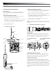
For best operation the receiver should be at least 3 ft. (1 m) above the
ground and at least 3 ft. away from a wall or metal surface to minimize
reections. The transmitter should be at least 3 ft. from the receiver,
as shown in Figure A. Keep antennas away from noise sources such
as digital equipment, motors, automobiles and neon lights, as well as
away from large metal objects.
Fig. A
Output Connections
There are two audio outputs on the back panel: balanced and
unbalanced. Use shielded audio cable for the connection between the
receiver and the mixer. If the input of the mixer is a
1
/
4
" jack, connect a
cable from the
1
/
4
" unbalanced audio output on the back of the receiver
housing to the mixer. If the input of the mixer is an XLR-type input,
connect a cable from the balanced XLR-type audio output on the back
panel to the mixer. The two isolated audio outputs permit simultaneous
feeds to both unbalanced and balanced inputs. For example, both a
guitar amp and a mixer can be driven by the receiver.
Antennas
Attach the included pair of UHF antennas to the antenna input jacks.
The antennas are normally positioned in the shape of a “V” (both 45°
from vertical) for best reception.
Accessory antennas can be remotely located from the receiver.
However, due to signal loss in cables at UHF frequencies, use the
lowest-loss RF cables practical for any cable runs over 25 feet. RG8-
type is a good choice. Use only copper-shielded cable, not CATV-type
foil-shielded wire. Audio-Technica offers quality RF cables in four
lengths, as well as remote antennas; see audio-technica.com for a wide
selection of wireless system accessories.
Antenna Power
The antenna input jacks also can provide +12V DC output on their
center pins to power inline RF devices. A maximum of 60 mA can be
drawn from each of the jacks. While an accidental short-circuit will not
harm the internal 12V supply, make certain that an antenna cable shield
does not contact the center conductor. Antenna Power is selected by
a switch on the back of the ATW-R2100b Receiver. The unit is shipped
with the switch in the “off” position.
Note: the antennas included with the ATW-R2100b Receiver do
not require power. If you have an antenna system that requires power
(such as powered antennas or active combiners or splitters) switch the
Antenna Power switch to the “on” position.
Power Connections
Connect the included AC adapter to the DC power input on the back of
the receiver. Loop the small cord from the DC plug over the cord hook
above the jack, to keep the plug from being detached by an accidental
tug on the cord. Operation of the receiver is controlled by the front-
panel Power switch.