Professional UHF Wireless Systems ATW-DA49 Diversity UHF Antenna Distribution System, 440-900 MHz Installation and Operation
Prior to use of this product, review all safety markings and instructions. CAUTION AVIS RISK OF ELECTRIC RISQUE DE CHOC SHOCK ÉLECTRIQUE DO NOT OPEN NE PAS OUVRIR To prevent electric shock, do not remove the cover. There are no user-serviceable parts inside. Internal adjustments are for qualified professionals only. Refer all servicing to qualified service personnel. Pour prévenir un choc électrique, ne pas ouvrir le couvercle. Il n’y aucune pièces de rechanges à l’intérieur.
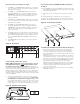
Rear Panel Controls and Functions (Fig. B) 3. 4. 5. CHANNEL “A” ANTENNA INPUT: Attach the “A” antenna here, or extend it with a low-loss antenna cable. (Antenna and cable not included.) CHANNEL “A” DISTRIBUTION OUTPUTS: Four jacks provide RF distribution to receivers operating within the 440-900 MHz range. Each output should be connected to only one other antenna input. Unused outputs do not require termination. Front-mount Antennas–ATW-RM1 Rack Mount Hardware Kit (Fig. D) 10.
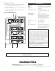
ATW-DA49 Set up (Fig. E) Specifications 12. +12V DC power is supplied through the ATW-DA49 Antenna Distribution System to each receiver. Bandwidth 440-900 MHz Gain 0 dB typical (within specified bandwidth) 13. Channel “B” distribution output connects to antenna “B” input jack on receiver. Impedance 50 ohms typical (within specified bandwidth) 14. Channel “A” distribution output connects to antenna “A” input jack on receiver.