2000 Series Professional UHF Wireless Systems ATW-2110 UniPak™ Transmitter System ATW-2120 Handheld Dynamic Microphone System Installation and Operation
Professional UHF Wireless Systems Installation and Operation This device complies with part 15 of the FCC Rules. Operation is subject to the condition that this device does not cause harmful interference. This device complies with INDUSTRY CANADA R.S.S. 210, en conformité avec IC: RSS-210/CNR210.
Receiver Installation Location For best operation the receiver should be at least 3 ft. (1 m) above the ground and at least 3 ft. away from a wall or metal surface to minimize reflections. The transmitter should be at least 3 ft. from the receiver, as shown in Figure A. Keep antennas away from noise sources such as digital equipment, motors, automobiles and neon lights, as well as away from large metal objects. Output Connections There are two audio outputs on the back panel: balanced (12.
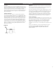
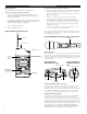
Receiver Controls and Functions Figure B-Front Panel Controls and Functions SET/SCAN UP POWER ON OFF UHF SYNTHESIZED DIVERSITY RECEIVER ATW-R2100 5 1 DOWN 2 3 1. POWER SWITCH: Press the Power switch in to turn the receiver on. The LCD window will light, and the operating channel number will be displayed in the window. To turn the receiver off, press the Power switch again. 4 5 Figure C-Receiver LCD Window Display 2.
Receiver Controls and Functions (Continued) Figure D-Rear Panel Controls and Functions 18 13 AF LEVEL ANT. B MIN MAX ANT. A SQUELCH 10 11 GROUND AF OUT GROUND LIFT BALANCED 12 14 15 12~18V DC AF OUT UNBALANCED 500 mA 16 17 10. ANTENNA INPUT JACK: BNC-type antenna connector for Tuner “B.” Attach the antenna directly, or extend it with a low-loss antenna cable. See the “Antennas” section on page 3 for more details. 15. BALANCED AUDIO OUTPUT JACK: XLRM-type connector.
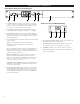
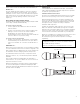
Transmitter Controls And Functions Battery Selection Two 1.5V AA alkaline batteries are recommended. UniPak™ Transmitter Battery Installation 1. Open the transmitter door by pressing gently on the side-cover indentations and pulling back the hinged cover shown in Fig. E below. 2. Lift the battery-keeper arm, and carefully insert two fresh 1.5V AA alkaline batteries, observing correct polarity as marked inside the battery compartment. 3. Close the battery-keeper arm.
System Operation The transmitters have a two-position, on-off power switch. When the switch is “On,” the transmitter produces both RF and audio. There is about a half-second delay after the transmitter is switched to the “On” position before the receiver’s Tone Lock squelch un-mutes the receiver.
System Operation (Continued) Setting Levels (Continued) ATW-T210 UniPak™ Transmitter Trimmer adjustments in the UniPak™ transmitter (Fig. E) will enable you to use microphones or instruments with different output levels. Figure E-UniPak Transmitter Open Antenna 1. For MIC: Set microphone level trim control fully clockwise (maximum) and instrument level trim control fully counterclockwise (minimum).
Specifications† OVERALL SYSTEM Operating Frequency Number of Channels Frequency Stability Modulation Mode Normal Deviation Operating Range Operating Temperature Range Frequency Response UHF band, 656.125 to 678.500 MHz 10 total ±0.
Optional System Accessories WIRELESS ESSENTIALS™ MICROPHONES AND CABLES AT829cW Miniature cardioid condenser lavalier microphone. Includes clothing clip and windscreen. MT830cW Miniature omnidirectional condenser lavalier microphone. Includes clothing clip and windscreen. MT830cW-TH “Theater” model, same as MT830cW except beige color mic and cable for concealment. AT831cW Miniature cardioid condenser lavalier microphone. Includes clothing clip and windscreen.
2000 Series Frequency Channel Plan Channel Frequency - MHz TV Channel 1 2 3 656.125 659.375 660.000 45 4 5 662.125 665.125 46 6 7 669.750 671.500 47 8 9 10 677.000 678.125 678.500 48 Note: All frequencies selected to avoid standard analog TV carrier interference. Ten Tips to Obtain the Best Results 2. Position the receiver so that it has the fewest possible obstructions between it and the normal location of the transmitter. Line-of-sight is best. 7.
One-Year Limited Warranty Audio-Technica professional wireless systems purchased in the U.S.A. are warranted for one year from date of purchase by Audio-Technica U.S., Inc. ( A.T.U.S.) to be free of defects in materials and workmanship. In event of such defect, product will be repaired promptly without charge or, at our option, replaced with a new product of equal or superior value if delivered to A.T.U.S.