
User Guide


ATC5488 TONE
GENERATOR
MODULE
INSTALLATION I NSTRUCTIONS
Thank
you
for choosing an Audio Telex
ATC5488 tone
generator
module. The ATC5488 has four tones available. These are
Evacuatim and Al€rt
Tones, both to A52220.1-2
standards, as
well
as a Bell Tone and
a Pre Announce
Chime.
lnstallation into
any
Audio Telex
manufuchred mixer or amplifier
is made simple by utilising a standard
'€nd'
qpe
connector
plug
supplied on the
module and a rec€ptacle, already installed
into the mixer or amplifier. Please follow these easy instructions for installation.
E The installation
of lhe ATC548E involvcs eccess to
thc
inside
of the rmplitrers
or mixerg Inst tlrtion
should only bc
rttemptcd by a
qualifed
technicirn. Alwlys
turn off the AC
power
and rcmove the AC
power
cord bcfore attempting
to scc.ss thc inside
of lhcsc
prodlcts.
Plerse contrct
your
Errest Audio
Telex
oftce for
detdls
of
your
trefcat
qualified
technicirn
'
For
installation into an
lC30
amplifier:
Locate the empty 7
pin
'and'
connector
receptacle on the mixer PCB to the left
of the
heat
sink
when
looking from the front
panel.
Connect the module to this receptacle, ensuring that the wires from the connector
exit
towards
the
rear
ofthe amplifier.
For installation into an
AT SERIES amplmer:
Lo€ate the empty 7
pin
'end'
connector receptacle on the mixer PCB between
the reble
pot
and the master
volume
pot.
Connect the module
lo this receptacle, orsuring that the wires from the connector exit
towards the right
hand side ofthe amplifier when
looking from tlre front
panel.
For
installation into an
SA SERIES amplifier: Locate the ernpty 7
pin
'end' connector receptacle on the mixer PCB
betweer
input
Ch. 6
pot
and the bass tonal contol
pot.
Connect
the
module to this receptacle, ensuring
that the wires
from the
conneclor exit towards the rear
ofthe amplifier.
For
lnstallatlon into a
TX6000
or
TX8000 mlxer: Locate the empty 7
pin
'end'
connector receptacle behind input
Ch. 5
pot
on
the mixer PCB. Comect the module to
this receptaclg ensruing that the wires from the connector
exit
towards the rear
of the
mixcr-
For
installaUon lnto a
TX8200 stereo mlxer: Locate the
eflpty
7
pin
'end'
corulector receptacle on the mixer PCB b€tween
input
Ch. 8
pot
and the Left
Channel Mast€r out
pot.
Connect the module
to this receptacle, ensuring that the wtes from
the
connector exit towards the rear
ofthe mixer.
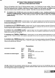
Connectlon to ampllfler:
Connections
Orange=
Output
Black
:
Grormd
Blue
=
Mute switch to I
Red = DC Supply
(Min.
I2VDC, Max. t SVDC)
Black = Common
White
=
Evac,uation Tone
Yellow: Bell
Tone
Purple
=
Alert Tone
Blue
=
Pre Annormce
Chime
Connectlons to swltched
signal:
Notes
Trim Pot Note
that the tim
pot
located
in
positim
RlO on the module attenuates the level out of the
ATC5488
and works in an
urti-clockwise fashion ie,
hnned
fully
clockwise will completely
att€nuate
the signal
outpl$
whilst
hrned fully anti-clockwise
will
allow full signal
present
though to
the
amplifier
stage.
r\'.1 ri