
Datasheet

K*R/P
2/Q
PLL_CLKIN
CODEC
CODEC_CLKIN
PLL_OUT
K=J.D
J=1,2,3,…..,62,63
D=0000,0001,….,9998,9999
R=1,2,3,4,….,15,16
P=1,2,….,7,8
Q=2,3,…..,16,17
MCLK BCLK
CLKDIV_IN
PLL_IN
WCLK =Fsref/ Ndac GPIO1 =Fsref/ Nadc
ADC_FSDAC_FS
Ndac=1,1.5,2,…..,5.5,6
DACDRA=>Ndac=0.5
Nadc=1,1.5,2,…..,5.5,6
ADCDRA =>Nadc=0.5
CODEC_CLK=256*Fsref
CLKDIV_OUT
1/8
PLLDIV_OUT
CLKDIV_CLKIN
2/(N*M)
CLKMUX _OUT
GPIO1
M=1,2,4,8
N=2,3,……,16,17
CLKOUT
CLKOUT_IN
TLV320AIC3107
SLOS545D –NOVEMBER 2008 –REVISED DECEMBER 2014
www.ti.com
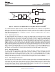
Feature Description (continued)
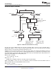
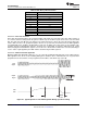
Figure 19. Audio Clock Generation Processing
The part can accept an MCLK input from 512 kHz to 50 MHz, which can then be passed through either a
programmable divider or a PLL, to get the proper internal audio master clock needed by the part. The BCLK
input can also be used to generate the internal audio master clock.
A primary concern is proper operation of the codec at various sample rates with the limited MCLK frequencies
available in the system. This device includes a highly programmable PLL to accommodate such situations easily.
The integrated PLL can generate audio clocks from a wide variety of possible MCLK inputs, with particular focus
paid to the standard MCLK rates already widely used.
When the PLL is disabled,
Fsref = CLKDIV_IN / (128 × Q) (1)
Where Q = 2, 3, …, 17
CLKDIV_IN can be MCLK or BCLK, selected by register 102, bits D7-D6.
NOTE – when NDAC = 1.5, 2.5, 3.5, 4.5, or 5.5, odd values of Q are not allowed. In this mode, MCLK can be as
high as 50 MHz, and Fsref should fall within 39 kHz to 53 kHz.
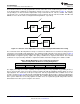
When the PLL is enabled,
Fsref = (PLLCLK_IN × K × R) / (2048 × P)
22 Submit Documentation Feedback Copyright © 2008–2014, Texas Instruments Incorporated
Product Folder Links: TLV320AIC3107