
Datasheet


TLV320AIC3107
SLOS545D –NOVEMBER 2008 –REVISED DECEMBER 2014
www.ti.com
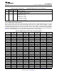
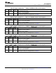
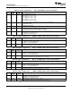
Table 83. Page 0 / Register 76: ADC DC Dither Control Register
BIT READ/ RESET DESCRIPTION
WRITE VALUE
D7-D4 R/W 0000 Left ADC DC Dither Level
0000: DC dither disabled
0001: DC dither 15 mV (differential) (minimum magnitude)
0010: DC dither 30 mV (differential)
0011: DC dither 45 mV (differential)
0100: DC dither 60 mV (differential)
0101: DC dither 75 mV (differential)
0110: DC dither 90 mV (differential)
0111: DC dither 105 mV (differential) (maximum magnitude)
1000: DC dither disabled
1001: DC dither -15 mV (differential) (minimum magnitude)
1010: DC dither -30 mV (differential)
1011: DC dither -45 mV (differential)
1100: DC dither -60 mV (differential)
1101: DC dither -75 mV (differential)
1110: DC dither -90 mV (differential)
1111: DC dither -105 mV (differential) (maximum magnitude)
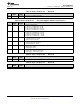
D3-D0 R/W 0000 Right ADC DC Dither Level
0000: DC dither disabled
0001: DC dither 15 mV (differential) (minimum magnitude)
0010: DC dither 30 mV (differential)
0011: DC dither 45 mV (differential)
0100: DC dither 60 mV (differential)
0101: DC dither 75 mV (differential)
0110: DC dither 90 mV (differential)
0111: DC dither 105 mV (differential) (maximum magnitude)
1000: DC dither disabled
1001: DC dither -15 mV (differential) (minimum magnitude)
1010: DC dither -30 mV (differential)
1011: DC dither -45 mV (differential)
1100: DC dither -60 mV (differential)
1101: DC dither -75 mV (differential)
1110: DC dither -90 mV (differential)
1111: DC dither -105 mV (differential) (maximum magnitude)
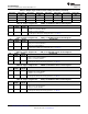
Table 84. Page 0 / Register 77: Reserved
BIT READ/ RESET DESCRIPTION
WRITE VALUE
D7–D0 R 00000000 Reserved. Do not write to this register.
Table 85. Page 0 / Register 78: Reserved
BIT READ/ RESET DESCRIPTION
WRITE VALUE
D7–D0 R 00000000 Reserved. Do not write to this register.
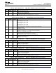
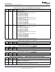
Table 86. Page 0 / Register 79: Reserved
BIT READ/ RESET DESCRIPTION
WRITE VALUE
D7–D0 R 00000000 Reserved. Do not write to this register.
Table 87. Page 0 / Register 80: LINE2L to LEFT_LOP Volume Control Register
BIT READ/ RESET DESCRIPTION
WRITE VALUE
D7 R/W 0 LINE2L Output Routing Control
0: LINE2L is not routed to LEFT_LOP
1: LINE2L is routed to LEFT_LOP
D6-D0 R/W 0000000 LINE2L to LEFT_LOP Analog Volume Control
For 7-bit register setting versus analog gain values, see Table 51
68 Submit Documentation Feedback Copyright © 2008–2014, Texas Instruments Incorporated
Product Folder Links: TLV320AIC3107