
User`s manual
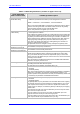
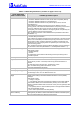
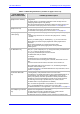
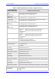
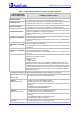
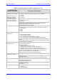
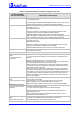
Table Of Contents
- Mediant 2000 & TP-1610 & TP-260/UNI SIP User’s Manual Version 5.0
- Table of Contents
- List of Figures
- List of Tables
- Notices
- 1. Overview
- 2. Physical Description
- 3. Installation
- 4. Getting Started
- 5. Web Management
- Computer Requirements
- Protection and Security Mechanisms
- Accessing the Embedded Web Server
- Getting Acquainted with the Web Interface
- Protocol Management
- Advanced Configuration
- Status & Diagnostic
- Software Update Menu
- Maintenance
- Logging Off the Embedded Web Server
- 6. Gateway's ini File Configuration
- Secured ini File
- Modifying an ini File
- The ini File Content
- The ini File Structure
- The ini File Example
- Networking Parameters
- System Parameters
- Web and Telnet Parameters
- Security Parameters
- RADIUS Parameters
- SNMP Parameters
- SIP Configuration Parameters
- Voice Mail Parameters
- ISDN and CAS Interworking-Related Parameters
- Number Manipulation and Routing Parameters
- E1/T1 Configuration Parameters
- Channel Parameters
- Configuration Files Parameters
- 7. Using BootP / DHCP
- 8. Telephony Capabilities
- Working with Supplementary Services
- Configuring the DTMF Transport Types
- Fax & Modem Transport Modes
- Event Notification using X-Detect Header
- ThroughPacket™
- Dynamic Jitter Buffer Operation
- Configuring the Gateway’s Alternative Routing (based on Conn
- Call Detail Report
- Supported RADIUS Attributes
- Trunk to Trunk Routing Example
- Proxy or Registrar Registration Example
- SIP Call Flow Example
- SIP Authentication Example
- 9. Networking Capabilities
- 10. Advanced PSTN Configuration
- 11. Advanced System Capabilities
- 12. Special Applications
- 13. Security
- 14. Diagnostics
- 15. SNMP-Based Management
- SNMP Standards and Objects
- Carrier Grade Alarm System
- Cold Start Trap
- Third-Party Performance Monitoring Measurements
- TrunkPack-VoP Series Supported MIBs
- Traps
- SNMP Interface Details
- SNMP Manager Backward Compatibility
- Dual Module Interface
- SNMP NAT Traversal
- SNMP Administrative State Control
- AudioCodes’ Element Management System
- 16. Configuration Files
- Appendix A. Selected Technical Specifications
- Appendix B. Supplied SIP Software Kit
- Appendix C. SIP Compliance Tables
- Appendix D. The BootP/TFTP Configuration Utility
- Appendix E. RTP/RTCP Payload Types and Port Allocation
- Appendix F. RTP Control Protocol Extended Reports (RTCP-XR)
- Appendix G. Accessory Programs and Tools
- Appendix H. Release Reason Mapping
- Appendix I. SNMP Traps
- Appendix J. Installation and Configuration of Apache HTTP Server
- Appendix K. Regulatory Information

SIP User's Manual 6. Gateway's ini File Configuration
Version 5.0 139 October 2006
Table 6-2: System Parameters (continues on pages 138 to 143)
ini File Field Name
Web Parameter Name
Valid Range and Description
MaxEchoCancellerLength
[Max Echo Canceller Length]
Note: It isn’t necessary to
configure the parameter
EchoCancellerLength as it
automatically acquires its
value from the parameter
MaxEchoCancellerLength.
Maximum Echo Canceler Length in msec:
0 = based on various internal gateway settings -- 64 msec (default)
4 = 32 msec
11 = 64 msec
22 = 128 msec
Note 1: When set to 128 msec, the number of available gateway channels is
reduced by a factor of 5/6.
For example:
Gateway with 8 E1 spans capacity is reduced to 6 spans (180 channels), while
gateway with 8 T1 spans capacity remains the same (192 channels).
Note 2: The gateway must be reset after the value of
‘MaxEchoCancellerLength’ is changed.
ECHybridLoss
Sets the four wire to two wire worst case Hybrid loss, the ratio between the
signal level sent to the hybrid and the echo level returning from the hybrid.
0 = 6 dB (default)
1 = 9 dB
2 = 0 dB
3 = 3 dB
GwDebugLevel
[Debug Level]
Defines the Syslog logging level (usually set to 5 if debug traces are needed).
0 = Debug is disabled (default)
1 = Flow debugging is enabled
2 = Flow and board interface debugging are enabled
3 = Flow, board interface and stack interface debugging are enabled
4 = Flow, board interface, stack interface and session manager debugging are
enabled
5 = Flow, board interface, stack interface, session manager and board interface
expanded debugging are enabled
CDRReportLevel
[CDR Report Level]
Determines whether or not CDRs are sent to the Syslog server, and if enabled,
at which events they are sent.
Valid options include:
0 = Call Detail Record (CDR) is not used.
1 = CDR is sent to the Syslog server at the end of each call.
2 = CDR report is sent to Syslog at the start and end of each call.
3 = CDR report is sent to Syslog at connection and at the end of each call.
The CDR Syslog message complies with RFC 3161 and is identified by:
Facility = 17 (local1) and Severity = 6 (Informational)
Note: This parameter replaces the EnableCDR parameter.
CDRSyslogServerIP
[CDR Server IP Address]
Defines the destination IP address for CDR logs.
The default value is a null string that causes the CDR messages to be sent with
all Syslog messages.
Note: The CDR messages are sent to UDP port 514 (default Syslog port).
HeartBeatDestIP
Destination IP address (in dotted format notation) to which the gateway sends
proprietary UDP ‘ping’ packets.
The default IP address is 0.0.0.0.
HeartBeatDestPort
Destination UDP port to which the heartbeat packets are sent.
The range is 0 to 64000.
The default is 0.
HeartBeatIntervalmsec
Delay (in msec) between consecutive heartbeat packets.
10 = 100000.
-1 = disabled (default).