
User`s manual
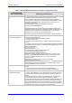
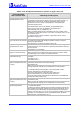
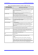
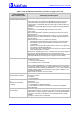
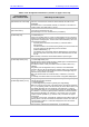
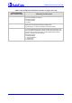
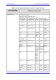
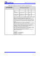
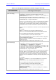
Table Of Contents
- Mediant 2000 & TP-1610 & TP-260/UNI SIP User’s Manual Version 5.0
- Table of Contents
- List of Figures
- List of Tables
- Notices
- 1. Overview
- 2. Physical Description
- 3. Installation
- 4. Getting Started
- 5. Web Management
- Computer Requirements
- Protection and Security Mechanisms
- Accessing the Embedded Web Server
- Getting Acquainted with the Web Interface
- Protocol Management
- Advanced Configuration
- Status & Diagnostic
- Software Update Menu
- Maintenance
- Logging Off the Embedded Web Server
- 6. Gateway's ini File Configuration
- Secured ini File
- Modifying an ini File
- The ini File Content
- The ini File Structure
- The ini File Example
- Networking Parameters
- System Parameters
- Web and Telnet Parameters
- Security Parameters
- RADIUS Parameters
- SNMP Parameters
- SIP Configuration Parameters
- Voice Mail Parameters
- ISDN and CAS Interworking-Related Parameters
- Number Manipulation and Routing Parameters
- E1/T1 Configuration Parameters
- Channel Parameters
- Configuration Files Parameters
- 7. Using BootP / DHCP
- 8. Telephony Capabilities
- Working with Supplementary Services
- Configuring the DTMF Transport Types
- Fax & Modem Transport Modes
- Event Notification using X-Detect Header
- ThroughPacket™
- Dynamic Jitter Buffer Operation
- Configuring the Gateway’s Alternative Routing (based on Conn
- Call Detail Report
- Supported RADIUS Attributes
- Trunk to Trunk Routing Example
- Proxy or Registrar Registration Example
- SIP Call Flow Example
- SIP Authentication Example
- 9. Networking Capabilities
- 10. Advanced PSTN Configuration
- 11. Advanced System Capabilities
- 12. Special Applications
- 13. Security
- 14. Diagnostics
- 15. SNMP-Based Management
- SNMP Standards and Objects
- Carrier Grade Alarm System
- Cold Start Trap
- Third-Party Performance Monitoring Measurements
- TrunkPack-VoP Series Supported MIBs
- Traps
- SNMP Interface Details
- SNMP Manager Backward Compatibility
- Dual Module Interface
- SNMP NAT Traversal
- SNMP Administrative State Control
- AudioCodes’ Element Management System
- 16. Configuration Files
- Appendix A. Selected Technical Specifications
- Appendix B. Supplied SIP Software Kit
- Appendix C. SIP Compliance Tables
- Appendix D. The BootP/TFTP Configuration Utility
- Appendix E. RTP/RTCP Payload Types and Port Allocation
- Appendix F. RTP Control Protocol Extended Reports (RTCP-XR)
- Appendix G. Accessory Programs and Tools
- Appendix H. Release Reason Mapping
- Appendix I. SNMP Traps
- Appendix J. Installation and Configuration of Apache HTTP Server
- Appendix K. Regulatory Information

SIP User's Manual 6. Gateway's ini File Configuration
Version 5.0 165 October 2006
Table 6-7: SIP Configuration Parameters (continues on pages 150 to 169)
ini File Field Name
Web Parameter Name
Valid Range and Description
MaxActiveCalls
[Max Number Of Active Calls]
Defines the maximum number of calls that the gateway can have active at the
same time. If the maximum number of calls is reached, new calls are not
established.
The default value is max available channels (no restriction on the maximum
number of calls). The valid range is 1 to 240.
MaxCallDuration
[Max Call Duration]
Defines the maximum call duration in minutes. If this time expires, both sides
of the call are released (IP and Tel).
The valid range is 0 to 120. The default is 0 (no limitation).
EnableBusyOut
[Enable Busy Out]
0 = Not used (default)
1 = Enable busy out
If Busy out is enabled, all E1/T1 trunks are automatically put out of service by
sending a remote alarm (AIS) or Service Out message for T1 PRI trunks that
support these messages (NI-2, 4/5-ESS, DMS-100 and Meridian), due to one
of the following scenarios:
• Physically disconnected from the network (i.e., Ethernet cable is
disconnected).
• The Ethernet cable is connected, but the gateway can't communicate with
any host. Note that LAN Watch-Dog must be activated
(EnableLANWatchDog = 1).
• The gateway can't communicate with the gatekeeper/proxy (according to
the Proxy keep-alive mechanism) and no other alternative exists to send
the call.
Note: The Busy out behavior varies between different protocol types.
EnableDigitDelivery2IP
[Enable Digit Delivery to IP]
0 = Disabled (default).
1 = Enable digit delivery to IP.
The digit delivery feature enables sending of DTMF digits to the destination IP
address after the TelÆIP call was answered.
To enable this feature, modify the called number to include at least one ’p’
character.
The gateway uses the digits before the ‘p’ character in the initial INVITE
message. After the call was answered the gateway waits for the required time
(# of ‘p’ * 1.5 seconds) and then sends the rest of the DTMF digits using the
method chosen (in-band, out-of-band).
Note: The called number can include several ‘p’ characters (1.5 seconds
pause).
For example, the called number can be as follows: 1001pp699, 8888p9p300.
EnableDigitDelivery
[Enable Digit Delivery to Tel]
The digit delivery feature enables sending of DTMF digits to the gateway’s B-
channel after the call is answered.
0 = Disabled (default).
1 = Enable Digit Delivery feature for gateway (two stage dialing).
Note: For incoming IPÆTel calls, if the called number includes the characters
‘w’ or ‘p’, the gateway places a call with the first part of the called number, and
plays DTMF digits after the call is answered. If the character ‘p’ (pause) is
used, the gateway waits for 1.5 seconds before playing the next DTMF digit. If
the character ‘w’ is used, the gateway waits for detection of dial tone before it
starts playing DTMF digits. The character ‘w’ can appear once in the called
number, and must precede any ‘p’ character. The ‘p’ character can appear
several times.
For example: if the number ‘1007766p100’ is defined as the called number, the
gateway places a call with 1007766 as the destination number, then, after the
call is answered, it waits for 1.5 seconds and plays the rest of the number
(100) as DTMF digits.
Other examples: 1664wpp102, 66644ppp503, 7774w100pp200.