
User`s manual


MP-1xx/H.323 User’s Manual 2. MP-10x Hardware Installation
Version 4.2 Beta 21 June 2003
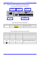
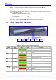
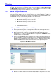
2.3 Rear Panel LED Indicators and Connectors
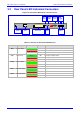
Figure 2-6: Rear Panel LED Indicators and Connectors
Table 2-3: Meaning of Rear Panel LED Indicators
Label Type Color State Meaning
Yellow ON Ethernet Port Receiving Data
ETH-1
Ethernet Status
Red ON Collision
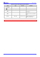
Table 2-4: Explanation of Rear Panel Connectors/Switches
Label Type Function Comment
100-240V ~ 1A
3-pin power inlet AC input Connection to external power supply
1 to 8
RJ-11 8 FXS or FXO Ports
MP-108 2-wire Loop Start interface
1 to 4
RJ-11 4 FXS or FXO Ports
MP-104 2-wire Loop Start interface
1 to 2
RJ-11 2 FXS Ports
MP-102 2-wire Loop Start interface
ETH 1
RJ-45 10/100 Base-T Port Shielded
RS-232
DB-9, DCE Status Messages
Gateway connects to PC’s RS-232 port with a
straight cable (refer to
Figure 8-1 on page 100).
Grounding screw Chassis Ground
MUST be securely connected.
10/100 Base-T
RJ-45 Port
9-pin RS-232
Status Port
RS-232
100-250 V ~1A
123456
7
8
ETH-1
1 to 8 FXS or FXS Ports
8 RJ-11 Ports
FXS or FXS
Power Supply
Inlet
Chassis
Ground Screw