
User`s manual


MP-124 H.323 User’s Manual 3. MP-124 Hardware Installation
Version 4.2 Beta 27 June 2003
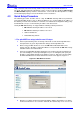
3.3 Rear Panel LED Indicators/Connectors
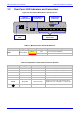
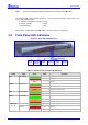
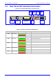
Figure 3-5: Rear Panel LED Indicators and Connectors
Data Cntrl Ready
CONFIG
1 2 3 4 5
ON
RS-232
Eth 1 Eth 2
ANALOG LINES 1-20
100 - 250V~
50 - 60Hz 2A
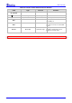
Table 3-3: Function of Rear Panel LED Indicators
Label Type Color State Function
Green ON Transmitting RTP Packets
Red ON Receiving RTP Packets
Data
Packet Status
Blank - No traffic
Green ON Currently not implemented
Red ON Currently not implemented
Cntrl
Control Link
Orange ON Currently not implemented
Green ON Device Powered and Self-test OK
Orange ON Software Loading/Initialization
Ready
Device Status
Red ON Malfunction
Green ON Valid link to 10/100 Base-T hub/switch
Eth 1
Ethernet Status
Red ON Malfunction
Green ON Valid link to 10/100 Base-T hub/switch
Eth 2
Ethernet Status
Red ON Malfunction
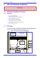
LAN
LED
s
Monitor
Port
Data
LED
50-pin Telco
Connector
AC Power
Inlet
Grounding
Screw
Eth 1 &
Eth 2
Cntrl
LED
Ready
LED