the minimoog synthesizer operation manual moog MUSIC INC. Academy Street (P.O.
A GUIDE TO THE OPERATION OF THE MINI MOOG MODEL D contents introduction basic mini moog features audio, control, and timing signals setting up the instrument output section oscillator bank controllers modulation mix others mixer modifiers filter and filter contour loudness contour accessories options s-trigger plug left-hand controller tuning procedures introduction An electronic music synthesizer is a musical instrument whose circuitry can be interconnected and set up in a large variety of ways to produc
basic mini moog features The Mini Moog contains the basic components and features to be found on larger, studiooriented synthesizers. Its five sound sources include three oscillators for the production of pitched tones, one noise source for the production of unpitched sounds, and one microphone preamplifier for the introduction of live signals. Mixer controls are available for balancing these signals. Sound modifiers include a lowpass filter and an amplifier, both of which have their own contour generators.
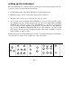
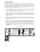
setting up the instrument Place the instrument at a convenient level for playing and secure the Front Panel in the "up" position by means of the metal bracket underneath. 1. Set all switches in the off position (left-hand or bottom half depressed). 2. Referring to Fig. 1, below, set all of the control knobs as indicated. 3. Plug the power cord into any conventional 117 Volt A.C. outlet. 4. Two 6’ patch-cords are supplied with the Mini Moog.
output section The Output section of the front panel includes two basic switches: the POWER switch, which turns the instrument on and off, and the MAIN OUTPUT switch, which sends the final audio signal out the MAIN OUTPUT jacks at the rear and into your amplifier. In addition, there are volume controls for the MAIN OUTPUT and HEADPHONE signals, and an A-440 switch, all of which will be described below. 1. Turn on the POWER switch (P).
oscillator bank This group of circuits contains three separate and independent oscillators. Each oscillator produces a waveform which repeats regularly, thereby giving rise to a tone of definite pitch. The audio signal outputs of the three oscillators are activated by turning on mixer switches (C), (E), and (G). Since switch (C) is now on, we are hearing the output of oscillator 1, which is the top row of controls (4, 5, and 12). 1.
controllers This section will demonstrate the use of the controls located to the left of the Oscillator Bank (used in tuning and setting up a sound), as well as the keyboard and the manual controls on the panel to its left (used during performance). All of these controls have an effect on the oscillators’ pitches, while the Modulation Mix and keyboard may also be used to control the filter.
9. Before continuing, defeat the oscillator modulation by turning off switch (A). other controllers 10. The PITCH wheel (28), located next to the MODULATION wheel to the left of the keyboard, is used to bend the pitch determined by the keyboard (as much as half an octave up or down) when the performer wishes to introduce expressive nuances to individual notes during performance. Depress a key, and move the PITCH wheel back and forth with your left hand.
mixer Audio signals produced by the three oscillators, noise source, and microphone preamplifier are combined and balanced by the Mixer section’s switches and volume controls. It is this composite signal, the output of the mixer, which is then modified by the filter and loudness contour controls and appears as the audio output signal of the Mini Moog. 1. The OSCILLATOR VOLUME controls (12, 13, and 14) are used to regulate the relative levels of the audio signals produced by the three oscillators.
modifiers The Modifiers section of the front panel features controls for the two sound modifiers, the Filter and the Loudness Contour, which respectively shape the overtone content and loudness/time contour of the audio signal as it passes through the modifying circuitry from the mixer.
TIME control from left to right. You will hear the brightness of the note increase sharply at first, and then more gradually as the attack time increases. 4. The DECAY TIME control (21) determines the duration of the second segment of the contour, the fall from the initial peak to the sustain level. The range of this control is about the same as that of the previous control. Set the DECAY TIME control at various levels moving slowly from left to right, while repeatedly depressing a key.
attenuated. To observe the effect of these switches, turn off Oscillator 1 (C) and the Filter Modulation switch (J), and set control (17) to 0. Turn on the NOISE SOURCE (F) and set the Noise Quality switch (H) to WHITE. This feeds white noise through filter and amplifier. Turn on switches (K) and (L) and play up and down the keyboard. You will hear the brightness of the white noise increase and decrease according to the position of the key which you have depressed.
loudness contour The volume of the audio signal which passes through the Modifiers section of the Mini Moog is contoured by the Loudness Contour controls. These controls are connected to a contour generator which supplies a control signal to the amplifier. Like the filter contour signal, the loudness contour signal is composed of three segments − initial rise, decay, and sustain level.
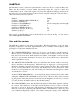
STANDARD ACCESSORIES SHIPPED WITH MINI-D SYNTHESIZER 1. Mini brochure & 1971 Catalog 2. Mini Instruction Manual 3. Warrantee (Reg. Postcard) 4. Shorting S-Trig Plug 5. "Back Panel Adjustment" Pamphlet 6. 6’ Phone Cord 7. 6’ Phone - Phono Cord 8.
OPTIONAL ACCESSORIES NOW AVAILABLE FOR USE WITH MINI MOOG MODEL D 1. 958 FOOT PEDAL This controller can be used to control the volume of the output, pitch of the oscillators, or the cutoff frequency of the filter (timbre). Up to three may be used simultaneously to control all of these functions. 2. 959 X-Y CONTROLLER This "joystick" simultaneously controls any two of the functions mentioned above. For instance, it can be used to produce vowel-like sounds by controlling the filter and pitch. 3.
S-TRIG PLUG FOR MINI MOOG MODEL D When inserted, this plug keeps the contour generators "on" continuously. It can be wired to an accessory foot switch for manual external triggering of notes.
LEFT HAND CONTROLLER EXTERNAL CONTROL OF GLIDE AND FINAL DECAY. The rocker switches in the left hand controller section have replaced the momentary push buttons used previously. Jacks have been added so that the performer can connect foot switches to engage GLIDE and DECAY functions. R. A. Moog will soon make these momentary switches available as an accessory. With no external switch connected and the GLIDE switch turned off there will be no portamento.
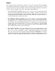
Mini Moog Model D Back Panel Adjustments (on instruments with serial number 1237 and higher) As with any fine musical instrument, the Mini Moog may require periodic tuning and adjustment. Holes in the back panel provide access to internal trim potentiometers for necessary adjustments. DO NOT ATTEMPT TO REMOVE THE BACK PANEL. This should be removed only by a qualified service technician.
8. Turn off reference oscillator. 9. Set OSCILLATOR 1 to 2´ range. 10. Turn on OSCILLATOR 2. 11. Tune OSCILLATOR 2 to OSCILLATOR 1, using OSCILLATOR 2 high end adjustment (C) . 12. Depress lowest A key and zero beat OSCILLATOR 1 with OSCILLATOR 2 using OSCILLATOR 2 low end adjustment (D). 13. Repeat steps 9 through 12 tuning OSCILLATOR 3 to OSCILLATOR 1. how to tune the filter (This is factory set and rarely, if ever, needs adjustment) 1. Set the front panel controls as shown in Figure 2. -1.1 7.