AudioContPOI® Making Good Sound Great™ Features ______ ..5 + ACM-4.300 Compact High Power 4-Channel Amplifier Four Channel Amplifier, 2 Ohm Stable, Active Speaker levellnputs, GTON Signal Sense, and 12 dB I Octave linkwitz-Riley Crossover High Current Design + Designed in the Pacific Northwest, USA www.audiocontrol.
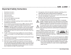
ACM-4.300 2 Important Safety Instructions 1. Read these instructions. 2. Keep these instructions. 3. Heed all warnings. 4. Follow all instructions. 5. Do not use this apparatus near water. 6. Clean only with a dry cloth. 7. Do not block any ventilation openings. Install in accordance with the manufacturer's instructions. 8. Do not install near any heat sources such as mufflers, silencers, exhaust pipes, or other apparatus (including amplifiers) that produce heat. 9.
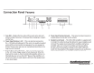
Connection Panel Features 2 3 4 5 1. Fuse 30A - Replace the fuse only with the exact same style and Ampere rating. Disconnect 12V power before changing or inspecting the fuse. 2. Power Input Terminal + 12V -This screw terminal connects to the+ 12V battery binding post of the vehicle. Use quality insulated wiring of the recommended wire gauge, such as wire gauge 8 or thicker. Thinner wire may cause an overheating hazard due to the large currents involved. 3.
ACM-4.3 00 4 6. RCA Analog Line-Level Inputs -The line-level outputs from the head unit or factory installed radios can connect here, so the ACM-4.300 will receive the line-level audio signals. Do not use the speaker-level inputs if you are using the RCA line-level inputs. 7. Speaker-Level Output Terminals -These screw terminals connect with speaker wire to your loudspeakers. Make sure that the average combined speaker impedance does not dip below 2 Ohms per channel.
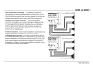
Control Panel Features GTOTM Signal Sense Protection Power High Pass Crossover I I •• ~On Off~ 80Hz BYPASS
-------------------------- -------------------------- -----ACnw-4.300 6 12. Gain Controls -These controls allows you to adjust the overall volume output level, with counterclockwise decreasing the volume, and clockwise increasing. One control is for channels 1 and 2, and the other for 3 and 4. The setting procedure is given on the next page, and involves nerves of steel, a steady hand, grit, determination, and the thought that you are making the world a better place. 13.
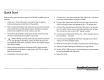
Quick Start Here are a few general steps to get your ACM-4.300 amplifier up and running: 7. Connect the+ 12V input terminal of the unit to the+ 12V terminal of the vehicle battery, using 8 to 4 AWG. 1. Undo the+ 12V and Ground connections to the car battery before making any connections to the amplifier. 8. Connect the Ground terminal of the unit to the chassis of the vehicle, using the same wire gauge as the+ 12V power wire. 2.
------- ------- ------- ------- ------- ------- ------- ------- -ACn w-4.3 00 8 Power Connections Head Unit 0 G> ACM-4.300 FourChanneiAmplif•tr. 20hmStiiible, GTO"'Signill Sense Act•vt:Speiiikerlevel lnput ~ . Remote Amplifier + 12V Trigger and 12 dB / Octilvtl•nkwitz-RileyCrossover DesignedinthePacificNorthwest . USA www.audiocontrol .com $pt"<~kf:t l-l lnpul~ 0 +12V G> ::: _____.
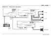
System #1: Using Speaker-Level Inputs 0 AucliiaConti'OI~ @ @ ACM-4.300 Four Channel Ampl ifier. 2 Ohm Stable. Active Speake r Level Inputs. GTO""SignaiSense and lldB /Octave lin kwlt Z-Ril ey Crossover + Desi gn ed tn + the Pacific Northwest. USA Fuse @ ~pe.ake 1 ACM-4.300 ·~+~ ~+~ www.audiocontrol.co m 0 O Le... ellnputs 30A + Speaker-level output 80Hz and above ~ ~===='---~-------+~ AUdiloContPol® Speaker-level 5 _____ outputs ACM-1 .300 Mono Subwoofer Amplifier ACM- 1.
ACM-4.300 10 System #2: Using Line-Level Inputs 0 AuctlloContftJI•@ --------~~------------- _____.,5 ACM- O 4:3aa· ~+~ four Channel Amplifier. 2 Ohm Stable :~~· ~; s;~~~t~:"ee~;~~~~:~-~~; ~~~~:~::~se + Des igned i.n the Pacific Northwest. USA www.aud•ocontrol.com ~ ... ~~~· ----., ' il.....,l J·$-_.. ~-~- 'i,.,..,.., t-- • o 0 0 0 0 0 0 ACM-4.300 @ ::: 0 ....
Cover Plate Removal The cover plate must be removed to gain access to the controls, and then put back on again to protect the controls from dust bunnies. ACM-4.300 Removal Procedure 1. Locate the top four screws that hold the cover plate in place. 2. Use a phil ips screwdriver to remove the four screws. 3. Keep the cover plate and screws in a safe and handy place, until you have finished adjusting the controls to your immense satisfaction. r: --------~1if-----------------~ , 8.910" ~~·- - 8-.
ACM-4.300 Specifications All specifications are measured at 14.4 VDC (standard automotive voltage). As technology advances, AudioControl reserves the right to continuously change our specifications, like our Pacific Northwest weather, although we are working on changing that as well. Protection Codes The ACM-4.300 Amplifier The various codes flashed by the Protection LED will help you diagnose any problems with your system. Power Output (RMS) ........................... 4x50 Watts@ 4 Ohms .............