TM ACCESS/A AUDIO CONTROL SYSTEM MODEL: A711 L-Series Operating Instructions TiL Document No. 09RE417 Rev. N/C January, 2011 Technisonic Industries Limited 240 Traders Boulevard, Mississauga, Ontario L4Z 1W7 www.til.
ACCESS/A A711 L-Series Operation Manual 09RE417 REVISIONS Revision Page Technisonic Industries ltd.
ACCESS/A A711 L-Series Operation Manual 09RE417 CAUTION This unit contains static sensitive devices. Wear a grounded wrist strap and work at a static-safe workstation when handling internal printed circuit boards. WARRANTY INFORMATION The Model A711L Audio Controller is under warranty for one year from date of purchase.
ACCESS/A A711 L-Series Operation Manual 09RE417 TABLE OF CONTENTS TiL DOCUMENT 09RE417 SECTION 1 GENERAL DESCRIPTION 1.1 1.2 1.3 1.4 1.5 1.6 Introduction ..................................................................................................................1-1 Description ...................................................................................................................1-1 Purpose of Equipment ................................................................................
ACCESS/A A711 L-Series Operation Manual 09RE417 LIST OF TABLES 1-1 A711L General Specifications .......................................................................................... 1-4 LIST OF ILLUSTRATIONS 1-1 1-2 2-1 2-2 2-3 2-4 2-4A 2-5 2-6 2-7 2-8 2-9 A711L Audio Control - General View................................................................................ 1-3 A711L Audio Control - General View................................................................................
ACCESS/A A711 L-Series Operation Manual 09RE417 SECTION 1 GENERAL DESCRIPTION 1.1 INTRODUCTION This publication provides operating and installation information on the Model A711 L-series, ACCESS/A Audio Controls manufactured by Technisonic Industries Limited. For convenience, it is referred to as the “A711L” in the manual. This unit is designed to provide high performance cockpit audio control in high noise installations.
ACCESS/A A711 L-Series Operation Manual 1.3 09RE417 PURPOSE OF THE EQUIPMENT The A711L ACCESS/A Audio Controls are designed to provide centralized audio management and control within an airborne communications environment. This includes radio and transceiver selection, intercom, airframe threat alerting, and crew management. These units have been packaged to minimize size and weight characteristics and are ideally suited for helicopter installations, or any other Dzus rail panel location.
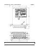
ACCESS/A A711 L-Series Operation Manual 09RE417 FIGURE 1-1 A711L ACCESS/A AUDIO CONTROLLER - GENERAL VIEW Technisonic Industries Ltd.
ACCESS/A A711 L-Series Operation Manual 1.5 09RE417 TECHNICAL SUMMARY A summary of the relevant electrical, operational, mechanical and physical characteristics of the control panels are given in Table 1-1, General Specifications. TABLE 1-1 A711 L-Series GENERAL SPECIFICATIONS MODEL A711 L-Series ACCESS/A Audio Controller: PHYSICAL CHARACTERISTICS: Width (max.)...........................................................................................................................5.
ACCESS/A A711 L-Series Operation Manual 1.6 09RE417 SYSTEM LIMITATIONS A summary of the relevant system limitations is given below. 1.6.1 Power Limitations With Standard Set-up, which consists of six headsets connected, a power output of not less than 332 mW is delivered per headset (as represented by 150 ohms) provided that the Direct Alert Input is terminated in not less than 600 ohms and that nominal input voltages are applied at the applicable channel inputs.
ACCESS/A A711 L-Series Operation Manual 1.6.4 09RE417 Isolation Limitations When in Pilot Isolation Mode, the pilot microphone for ICS operation is rendered inactive. Consequently, neither co-pilot nor passengers can receive pilot intercom transmissions while the latter is in Isolation mode. 1.6.5 Standard Settings Utilised Throughout Testing Pilot Headset Settings utilized throughout testing was for the standard 150 ohms impedance headset.
ACCESS/A A711 L-Series Operating Instructions 09RE417 SECTION 2 OPERATING INSTRUCTIONS 2.1 FRONT PANEL OPERATORS SWITCHES AND CONTROLS This section explains the operation of the A711L ACCESS/A Audio Controls, and how to use the system in a typical aircraft environment. All normal user controls are on the front panel of the unit and are either variable rotating controls, or selectable push-button switches.
ACCESS/A A711 L-Series Operating Instructions 2.1.1 09RE417 • Any combination of RX sources may be selected at one time, for system monitoring purposes. Multiple TX destinations may also be selected by pressing in two or more buttons simultaneously to set up simulcast operation. Pressing any TX button in automatically resets any previous selection, but RX selections are independent push on/push off switches.
ACCESS/A A711 L-Series Operating Instructions 2.1.2 09RE417 ICS or INTERCOM VOLUME CONTROL The ICS LEVEL knob controls the intercom volume level for all users. Fully clockwise is the maximum volume level and counter-clockwise the minimum. The ICS volume can be set to zero, but has the internal capability to be preset to a low minimum value, if desired.
ACCESS/A A711 L-Series Operating Instructions 2.1.4 09RE417 RX or RECEIVE SELECTORS & LEVEL CONTROLS These 7 push-button RX SELECTOR switches allow the crew to monitor any combination of the Receivers in the airframe system, independent of the setting of the transceiver selectors. The RX SELECTORS have an alternate action; push in to activate the audio, push again to have the switch return to the out position and off. Any number or combination of RX switches may be used at the same time.
ACCESS/A A711 L-Series Operating Instructions 2.1.6 09RE417 TX or TRANSCEIVER SELECTORS FIGURE 2-5 A711L TX SELECTORS The setting of the TX SELECTOR switches determines which Transceiver will transmit the activated microphone audio, and which receiver the system will monitor, independent of the additional RX switch settings. The buttons have an interlocking action, and pressing one button will automatically de-select any other that is already activated.
ACCESS/A A711 L-Series Operating Instructions 2.1.7 09RE417 EMERGENCY SWITCH OPERATION & STATUS LEDs The operation of the A711L control can be changed from NORMAL to EMERGENCY operation in two different ways. First, if DC power fails to the unit, the internal auto-emergency function is enabled; this transfers the unit to a passive emergency mode to enable critical communication to continue for the pilot.
ACCESS/A A711 L-Series Operating Instructions 2.1.8 09RE417 A711L PA CONTROLS The A711L control differs slightly from the other A710/A711 series in that a single button transfer is incorporated for shifting from any preset TX mode to PA mode, and back again. This allows simulcast settings to remain undisturbed and provides a very fast way of shifting TX modes in flight. PA operation has some hazards for the flight crew, however.
ACCESS/A A711 L-Series Operating Instructions 2.2 09RE417 SPECIAL SIGNAL CONSIDERATIONS There are several special signals and lines related the A711L, which require careful installation planning, and understanding by the flight crew. 2.2.1 DIRECT AUDIO CONNECTIONS The A711L has two different un-switched, direct audio inputs. One is routed directly to the Pilot’s headset output via a resistive pad.
ACCESS/A A711 L-Series Operating Instructions 2.2.3 09RE417 TONE ALERTING The A711L supports the installation of optional tone alerting. The alerting tones function as follows: Alerting tones are activated by a ground trigger at the corresponding input pin, and play once the alert line is triggered. The #3 (DH) alert is timed, and the #2 alert, (Low Rotor) over-rides tone #1 (Engine Failure).
ACCESS/A A711 L-Series Operating Instructions 2.3 09RE417 CHANGING OVERLAY LIGHTING & RADIO LEGENDS The legends on the A711L front panels, and the overlay color and lighting type can all be easily changed in the field to suit special requirements. The entire lighted overlay is changed by removing three screws, as illustrated below. Remove the knobs (use an Allen/Hex key to undo the set screws), and the overlay assembly will pull off.
ACCESS/A A711 L-Series Operating Instructions 09RE417 2.4 Product Warranty Terms Technisonic Industries Limited 240 Traders Blvd., Mississauga, ON Canada L4Z 1W7 Tel: (905) 890-2113 Fax: (905) 890-5338 IMPORTANT! PRODUCT WARRANTY All communication equipment manufactured by Technisonic Industries Limited is warranted to be free of defects in Material or Workmanship under normal use for a period of one year from Date of Purchase by the end user.