
Service manual

F - 18 Tait Orca vehicle kit June 2003 IPN: M5000-00-105
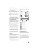
Table F-9: Vehicle kit power connector
(SK1 on the charger PCB)
Table F-10: Vehicle kit mobile microphone connector
(SKT1 on the options PCB)
Table F-11: Vehicle kit accessory/data connector
(SK3 on the charger PCB)
Pin Signal Description
1N/C–
2 GND Main ground connection
3 IGN Switched accessory power -
connect to permanent power to dis-
able ignition sense
4 +13V8 Main connection to +13.8 V (vehicle
battery). Use 3 A fuses.
Pin Signal Description
1 +13V8LIM Power out
Zout = 10 Ω; 100 mA maximum
2N/C–
3 EXT-PTT External PTT and function buttons*
* EXT-PTT is pulled high inside the radio by 27 kΩ.
Function buttons are implemented by pull-downs to
ground. For BUTTON-1, R = 12 kΩ; for BUTTON-2, R
= 27 kΩ.
4 MOB-MIC Dynamic microphone input imped-
ance = 600 Ω
5GNDGround
6N/C–
Pin Signal Description
1GNDSignal ground
2 RX-IN RS-232 Receive data to radio
3 TX-OUT RS-232 Transmit data from radio
4N/C–
5 BUSY Radio receiving
low = busy (including beeps)
6 AUDIO-D25 Single ended audio.
Zout = 3 kΩ; AC coupled
7GNDSignal ground
8 EXT-MIC-D25 Microphone input
Zin = 1 kΩ
9 MOD-AUDIO To modulator
10 EXT-PTT PTT and function buttons
low = PTT
11 SPKR-OFF Turns radio and external speaker
off
low = off
12 RX-DET-AF Detected receive audio (unmuted)
13 GND Signal ground
14 +5V 5 V power
25 mA maximum
15 +7V5-ACC 7.5 V from radio
25 mA maximum
16 SENSE-0-
ACC
Radio internal speaker control
low = off
17 SENSE -1-
ACC
–
18 SPKR+ Balanced output from audio PA
19 SPKR- Balanced output from audio PA
20 N/C –
21 N/C –
22 N/C –
23 N/C –
24 LVSD Low voltage shut down - turns off
vehicle kit
25 +13V8FILT 13.8V power
500 mA maximum