
Service manual


June 2003 IPN: M5000-00-105 Circuit descriptions B - 13
Circuit descriptions
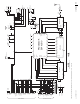
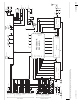
Circuit interface diagrams for the Tait Orca
portable radios are shown in Figure A-1 (TOP
B, C, G, H, I, J and K) and Figure A-2 (TOP A
only).
The Tait Orca portable radio has been
designed to be totally electronically tuned
using the Calibration Application. The titles of
tests referred to below are tests available in the
calibration system, e.g. Power Level test
refers to the Power Level screen in the calibra-
tion system. Consult the Calibration Applica-
tion online help or User’s Manual for more
information on specific calibration tests.
Transmitter
The RF power amplifier amplifies transmit RF
from the VCO to the output power level (3W
800/900 MHz, 4W UHF, 5W VHF). The PA
output is fed to the PIN switch, which provides
isolation between the transmit and receive
paths.
An LPF follows the PIN switch and provides
attenuation of unwanted high frequency
signals.
Following the LPF, the signal is fed to the
antenna.
The output power level is controlled by the
microprocessor and associated circuitry, and
is initially set by calibrating the radio (Power
Level test).
Transmit (Tx) audio
Tx audio from the microphone is processed by
the DSP and associated circuitry into two
modulation signals, one required by the TCXO
in the synthesiser and the other by the VCO.
A digital pot is used to set the overall deviation
and modulation balance; these are controlled
by calibration (Maximum Deviation and
Modulation Balance tests).
Receiver
RF from the antenna is fed via the LPF and PIN
switch into the receiver. The RF passes through
the front end tuning circuit, which rejects
unwanted frequencies. The front end is
electronically tuned, and the front end tuning
voltage that sets the centre of the bandpass
filter is determined during calibration (Front
End Tuning test).
The output of the front end tuning stage is fed
to the first mixer, and the VCO provides the
local oscillator input. The output of the mixer
is at the first IF frequency (45.1 MHz UHF/
21.4 MHz VHF).
The IF signal passes through two crystal filters,
separated by the IF amplifier.
In the Demod IC, the signal passes through the
second mixer, producing the second IF (455
kHz). The second IF passes through a ceramic
band pass filter and IF amp, which are external
to the IC. The second IF is then fed back into
the Demod IC for another amplification stage,
then through another ceramic band bass filter.
The final stage is the phase lock loop (PLL)
discriminator in the Demod IC, which produc-
es detected audio.
A squelch detect circuit detects high frequency
audio noise and compares it with a threshold
(programmable as city or country for each
channel), which is set up by the microproces-
sor. The squelch level can be set during calibra-
tion (Squelch Thresholds test).
The RSSI output of the detector circuit
provides an analogue indication of the
received signal strength. RSSI thresholds are
set during calibration (RSSI Thresholds test).
Receive (Rx) audio
The detected audio is processed by the DSP,
amplified and fed to an internal speaker,