
Service manual

June 2003 IPN: M5000-00-105 Replacing key mechanical and ancillary devices D - 11
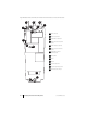
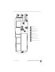
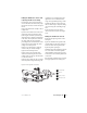
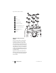
Figure D-9: Top surface of PCB, which is visible only when the PCB has been removed from the chassis
123
4
5
6
7
8
9
antenna connector
channel selector switch
on/off/volume control switch
RF assembly placement
auxiliary flex socket
PTT tact pin placement (4 pins)
battery contact placement
battery contact seal placement
microphone pin placement (2 pins)
1
2
3
4
5
6
7
8
9