
Service manual

D - 12 Replacing key mechanical and ancillary devices June 2003 IPN: M5000-00-105
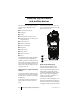
Replacing the shield, user interface
PCB and polyester dome (Orca
5015/2x/35/40)
On Orca 5015/2x/35/40 radios the shield, user
interface PCB and polyester dome are replaced
as one complete assembly.
Following the disassembly instructions, remove
the shield from the front panel and unplug the
user interface loom from the user interface
PCB.
Remove the LCD display assembly from the
discarded shield, and fit to the replacement
shield according to the instructions on page D-
9.
Plug the user interface loom into the connector
on the new user interface PCB, and reassemble
the shield onto the chassis according to the
instructions on page D-15.
Replacing the antenna connector,
channel selector switch and volume
control switch
Following the disassembly instructions, disas-
semble the radio to the PCB level. Remove the
PCB from the chassis.
If any of the antenna connector, channel selec-
tor switch or volume control switch need to be
replaced, remove them using a vacuum-
operated solder station. Replace them accord-
ing to the reassembly instructions on pages D-
14 to D-17.
Replacing the microphone
Following the disassembly instructions, disas-
semble the radio to the PCB level. Remove the
PCB from the chassis.
Use a desoldering station to remove the micro-
phone. Discard the microphone.
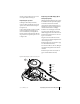
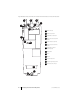
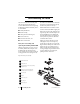
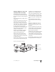
When replacing the microphone, make sure it
is aligned with the marks on the PCB, since it is
polarised. Refer to Figures D-8 and D-9 for the
placement of the microphone.
The microphone should not hang over the
edge of the PCB. Solder it in place using a light-
tip soldering iron (e.g. Weller PTR7 tip).
Replacing the battery and speaker
contacts
Following the disassembly instructions, disas-
semble the radio to the PCB level. Remove the
PCB from the chassis.
When replacing one of the battery or speaker
contacts, replace the other contact, even if only
one is faulty. If available, use solder paste to
replace the contacts.
Note that the contacts are heat-sensitive and
will fail if they are overheated.Low tempera-
ture solder must be used and the contacts must
not be heated above 260°C.
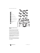
Remove the contact with a soldering iron and
discard. Refer to Figures D-7 and D-8 for the
placement of the battery and speaker contacts.
Solder the replacement contact in place using a
heavy-tip soldering iron (e.g. Weller 2PTCC8
tip). Hold onto the contact with a pair of pliers
and apply large amounts of solder to the PCB,
rather than to the contact, to avoid damaging
the contact.
Replacing the tact switch
Following the disassembly instructions, disas-
semble the radio to the PCB level. Remove the
PCB from the chassis.
Remove the PTT tact switch using a desolder-
ing station or solderwick. Note that there is a
lot of solder on both sides of the board, so be
sure to remove it all.
Refer to Figures D-8 and D-9 for the placement
of the PTT tact switch.
Place the new PTT on the board and solder it in
place using a heavy-tip soldering iron (e.g.
Weller 2PTCC8 tip).