
Service manual

D - 14 Reassembling the radio June 2003 IPN: M5000-00-105
Reassembling the radio
This section describes the reassembly of the
radio once the required units have been
serviced. Additional instructions for replacing
the following mechanical and ancillary devices
are also included:
■ auxiliary flexible PCB;
■ RF out assembly;
■ volume plate and volume keypad;
■ antenna connector;
■ channel selector switch; and
■ volume control switch.
Rear panel reassembly and
replacing the auxiliary flexible PCB
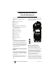
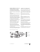
Follow the instructions on page D-7 to access
the auxiliary flexible PCB, and replace. Push
the flexible PCB with seal firmly into the
chassis, aligning the notch in the seal with the
locating pin on the chassis (see Figure D-10).
The rubber must sit flush with the back of the
chassis or the rear panel will not sit properly
and the battery will not fit correctly.
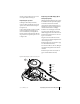
Fold the flexible PCB over and fit the contact
area on the chassis; it should fit snugly in place.
Replace the rear panel seal by tucking the two
tags at the top of the seal under the lip on the
chassis and folding it over the flexible PCB.
Check that the RF contact pin is positioned
correctly in the rear panel seal, and that the
seal is flush with the chassis.
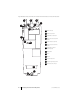
Slide the rear panel on from the top of the
radio (Figure D-10). Force it into place by
pressing the top edge of the cover against the
edge of a table; it will clip home. Make sure the
gap between the cover and the chassis is as
small as possible. Refit the auxiliary dummy
cover by pushing the lugs into the holes on the
rear panel. Replace the chassis plug seal,
pushing it onto the chassis boss.
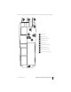
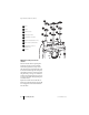
Figure D-10: Rear panel assembly
auxiliary flexible PCB
auxiliary flex seal
end of auxiliary flex connector protruding
through the seal
make sure the seal and auxiliary flex
are firmly seated in the chassis here
rear panel seal
chassis
replace rear panel
RF contact pin
chassis plug seal
1
2
3
4
5
6
7
8
9
9
8
7
6
5
4
3
2
1