
Service manual

E - 6 Desktop fast charger June 2003 IPN: M5000-00-105
Desktop fast charger
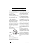
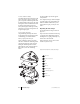
The Tait Orca desktop fast charger (Figure E-1)
is an intelligent charger that can charge, condi-
tion and analyse both NiCd and NiMH batter-
ies of varying capacities.
Fast charger operation
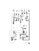
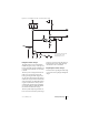
A circuit diagram of the fast charger is shown
in Figure E-2. The fast charger operates using
constant current charging and multiple crite-
ria for end-of-charge detection. When a
battery is inserted, the charger detects the type
of battery, checks to see if it is working correct-
ly, and then charges the battery.
If the conditioning button is pressed after
inserting the battery, the charger will
discharge the battery before charging. If the
conditioning button is held down while the
battery is being inserted, the charger will enter
a long condition cycle that will charge and
discharge the battery a number of times and,
on the last cycle, check its capacity before
recharging.
Multiple protection methods are employed to
ensure safe operation.
Figure E-1: Tait Orca fast charger
Hardware operation
Power to the unit is provided from a 12 volt,
1 amp (nominal) wall-mounted AC to DC
adaptor, through SK1. Reverse polarity protec-
tion is provided by the 22 V transient suppres-
sor, D1, in conjunction with PolySwitch™ PS1.
Under reverse polarity conditions, D1
conducts, drawing the available short circuit
current until PS1 trips. D1 also protects
against any voltage spikes that may come
through the AC to DC adaptor. The unit is
designed for 10.5 - 14 V operation.
The +5V supply is produced by the regulator,
IC1. A feature of this regulator is that it
provides a RESET output to the microproces-
sor. This RESET output is used to delay startup
of the microprocessor until the power supply
has stabilised after turn-on. It also puts the
microprocessor into reset if the input voltage
falls too low. D2 sets this low voltage threshold
to approximately 9.2 V.
The intelligence of the fast charger is provided
by the microprocessor, IC2, which interfaces
with the current source, the discharge circuit
and the expanded battery voltage interface. The
user can interact with the fast charger by press-
ing the conditioning button, SW1, and can
observe the operational state on the tri-colour
LED, D5.
The current source is based on a ground-
sensing linear topology. R1 and R2 are the
current sense resistors. The power device is a
P-channel MOSFET, Q4, which is controlled
by an operational amplifier, IC3:A. The
feedback path that controls the op amp, and
hence the current, is through transistor Q5
and its resistor network. The grounding on
R23 includes the ground sense resistors in the
feedback path. The nominal output current is
800 mA.
r
LED
Conditioning
button