
System information


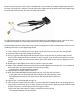


47. Reconnect the original J10 and J11 ribbon cables so the assembly process between the two boards is
now complete.
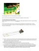
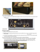
48. Copper Tape. (see photograph on page 12)
Take one piece of copper tape, the other is a spare, and peel the backing o the self-sticking adhesive
copper tape, form the tape to an “L” shape, and press the tape into the gap between the USB
connector and the rear panel as shown below to ensure the gap is sealed.
Caution: the edge of the copper is sharp, be careful not to cut yourself!
The Internal installation is now complete.
Final assembly procedure for both Type A and Type B models
Below are the nal steps to nishing your Mark II upgrade. These steps apply to both the type A and the
type B installation procedures.
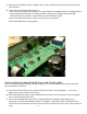
49. Secure the XLR connector to the rear panel with the two M2.5 screws (pentagons). Do not over
tighten, these screws only need to be snug.
50. Secure the optical connector to the rear panel with the 4-24 X 3/8” Screw (circle). Do not over tighten,
these screws only need to be snug.
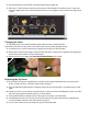
51. Secure the two HDMI connectors to the rear panel with the two M3-0.5 X 6mm Phillips screws
(diamonds). The tabs on the HDMI connectors are fragile so support them with your nger on the
inside of the rear panel while you start the screw into the connector tab. These screws only need to be
snug.
J11
Copper Tape J10