
User's Manual

After selection of the mounting location, mark the hole to
be cut out. A template is provided in the speaker box.
Locate and align the template, then mark with pencil on
the ceiling surface. If you are unsure whether there are
obstructions behind the ceiling surface where the
speakers are to be mounted cut a small hole in the
center of your marked mounting location. Holding your
drywall saw at a 45 degree angle (See Fig. 2) cut a
square hole that you can use to locate any obstructions,
should they exist.
The 45 degree wedge shape of the removed surfacing
material will make replacement, if necessary, a much
easier task and yield a better finish when patching the
work.
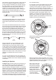
Once it has been determined that there are no obstruc-
tions cut the hole to mount the speaker using the drywall
saw at a 90 degree angle to the ceiling surface. Cover
the raw edges of the wallboard with masking tape
(See Fig. 3). This will prevent the back pressure of the
speaker from blowing loose gypsum dust out and on to
the painted ceiling surface after installation. Do not allow
the tape to extend more than 1/4” beyond the edge of
the hole into the room. The frame of the AS6c will cover
and hide the tape.
Next you will want to run your speaker wire to your
speaker locations. A UL rated CL3 speaker wire is
recommended when running wire inside your walls.
In many areas it may be required by code. When running
your speaker wire you should avoid having the speaker
wire run parallel to the 110V power lines to avoid picking
up hum and interference from the power service. If the
speaker wire needs to cross a 110V power line at a right
angle this is acceptable and should not create a
problem.
If you are uncomfortable with running the speaker wire
yourself in existing construction, it is recommended that
you retain a qualified custom home installation specialist
or electrician.
Installing the Speakers
Installation Tip! To further enhance the performance of
your AS6c speakers, the ceiling joist cavity where you
plan to place your speakers can be stuffed with a
generous quantity of fiberglass insulation. If uninsulated,
stuff the area in front of and behind the speaker opening
with 6” thick insulation to a depth of approximately 2 feet
beginning 1 foot in front of and 1 foot behind the speaker
opening. If the insulation is foil or paper backed, face the
backing away from the AS6c speaker. The addition of
this insulation will help to prevent the unwanted transfer
of sound into the otherwise large and resonant cavity of
ROOM
Figure 3
ROOM
Masking T.ape
Figure 2
the uninsulated ceiling.
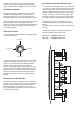
It is now time to connect the speaker wire to the AS6c.
Your speaker wire is usually coded to identify each
conductor as either positive or negative. This can be by
color coding, or one conductor may have a printed
marking or at least a rib along one edge that you will not
find on the other. Identify which type of polarity coding
that your wire is using. You must carefully observe that
the positive terminal of the speaker output on your
amplifier is connected to the positive terminal of the
AS6c speaker. Likewise, the negative terminal of the
amplifier’s speaker output should be connected to the
negative terminal of the AS6c speaker.
Next make sure that the doglegs are positioned inside
the frame of the speaker.
With the grill removed, place the speaker in the ceiling
opening. Make sure that the speaker wire is not hanging
against the speaker where it can vibrate and rattle as the
speaker reproduces your audio program.
Next, one at a time, turn
each of the four screws
that operate the doglegs
counter clockwise a few
turns until you feel the
dogleg is loose from its
resting position. Now turn
the screw clockwise until
you feel the dogleg
contact the wall surface.
(+) Amp
(-) Amp
Correct
2
1
2
3
4
Incorrect
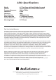
AS6c
6.5” Two Way In-Ceilling
100W / 8 ohm
AS6c
6.5” Two Way In-Ceilling
100W / 8 ohm