deutsch / english UP 10DSP UPGRADE 10-Kanal Upgrade-Verstärker mit integriertem 11-Kanal 64 Bit DSP für universelle Anwendungen 10-channel upgrade amplifier with integrated 11-channel 64 Bit DSP for universal applications
Herzlichen Glückwunsch! Sehr geehrter Kunde, wir gratulieren Ihnen zum Kauf dieses hochwertigen MATCH Verstärkers mit integriertem DSP. MATCH setzt mit dem UP 10DSP neue Maßstäbe im Bereich der Verstärkertechnik. Dabei profitieren Sie als Kunde direkt von unserer mehr als 30-jährigen Erfahrung in der Forschung und Entwicklung von Audiokomponenten.
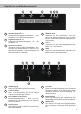
Anschluss- und Bedienelemente 1 2 3 1 Speaker Output E - J Lautsprecherausgänge der Kanäle E - J zum Anschluss von Lautsprechersystemen. 2 Highlevel Input E - H Hochpegel-Lautsprechereingang Kanäle E - H. 3 System Connector Anschluss für den MATCH Kabelbaum. Verwenden Sie ausschließlich ein MATCH Original-Anschlusskabel, um den Verstärker mit dem Autoradio zu verbinden. 7 8 für die 9 4 5 6 4 REM IN / OUT Anschluss für den Remote-Ein- und Ausgang.
Inbetriebnahme und Funktionen 1 Speaker Output E - J Diese Anschlüsse dienen als Lautsprecherausgänge. Die Impedanz der Lautsprecher darf 4 Ohm für die Ausgänge E - H und 2 Ohm für die Ausgänge I & J nicht unterschreiten. Achtung: Es wird dringend empfohlen, vor der ersten Inbetriebnahme mit der DSP PC-Tool Software die grundlegenden Einstellungen im Verstärker vorzunehmen. Eine Missachtung kann zur Zerstörung der angeschlossenen Lautsprecher führen.
sene Verstärker einzuschalten! 5 +12 V Anschluss für das +12 V Versorgungskabel. Das Kabel ist am Pluspol der Batterie anzuschließen und sollte einen empfohlenen Querschnitt von mindestens 6 mm² aufweisen. 6 GND Das Kabel sollte am zentralen Massepunkt (dieser befindet sich dort wo der Minuspol der Batterie zum Metallchassis des Kfz geerdet ist) oder an einer blanken, von Lackresten befreiten Stelle des KfzChassis angeschlossen werden. Der empfohlene Querschnitt beträgt mindestens 6 mm².
Inbetriebnahme und Funktionen des / der angeschlossenen Verstärker/s zu verwenden, da ansonsten Störgeräusche auftreten können. Der Remote-Ausgang schaltet sich automatisch während des Power Save Modus sowie bei einem Software-Update ab. Das Audiosignal kann mit Hilfe der DSP PC-Tool Software unabhängig von den anderen Verstärkerkanälen konfiguriert werden.
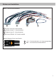
Einbau und Installation Abb. 1: Übersicht Anschlusskabel 1 2 3 1 System Connector Anschlusskabel 2 Speaker Output E - J Anschlusskabel 3 Highlevel Input E - H Anschlusskabel 4 Remote (REM IN / OUT) Anschlusskabel 4 Abb. 2: Belegung Power Input Stecker A A +12 V – Zum Anschluss des +12 V Versorgungskabels. B GND – Zum Anschluss des Massekabels.
Einbau und Installation Abb. 3: Pinbelegung UP 10DSP SPEAKER OUTPUT HIGHLEVEL INPUT SYSTEM CONNECTOR 29 30 31 32 33 34 21 22 23 24 1 35 36 37 38 39 40 25 26 27 28 11 12 13 14 15 16 17 18 19 20 2 3 4 5 6 7 REM IN 8 9 POWER INPUT +12V GND 10 OUT System Connector 1. Highlevel-Lautsprechereingang hinten links (-) / C 2. Highlevel-Lautsprechereingang vorne links (-) / A 3. Highlevel-Lautsprechereingang vorne rechts (-) / B 4. Highlevel-Lautsprechereingang hinten rechts (-) / D 5.
Der MATCH UP 10DSP Verstärker wird wie nachfolgend beschrieben montiert und angeschlossen. Achtung: Für die Durchführung der nachfolgenden Schritte werden Spezialwerkzeuge und Fachwissen benötigt. Um Anschlussfehler und Beschädigungen zu vermeiden, fragen Sie im Zweifelsfall Ihren Fachhändler und beachten Sie zwingend die allgemeinen Anschluss- und Einbauhinweise (siehe Seite 2). 1. Anschluss des System Connector 1.
Einbau und Installation bedeutet, dass an sämtlichen Ausgängen der UP 10DSP der volle Pegel anliegt. Dies kann im Extremfall die angeschlossenen Lautsprecher zerstören. Wir raten deshalb dringend dazu, eine optionale Fernbedienung zur Einstellung der Lautstärke der digitalen Signaleingänge zu verwenden! Hinweis: Die UP 10DSP kann nur unkomprimierte, digitale Stereo PCM-Signale mit einer Abtastrate zwischen 12 kHz und 96 kHz verarbeiten.
2. Wählen Sie das Setupverfahren zur Einstellung der Eingangsempfindlichkeit aus. Standard Gain Setup: Hier kann die Eingangsempfindlichkeit global für alle Kanäle eingestellt werden (nur bei „Low Voltage Range“ Jumper-Steckposition – siehe links). Advanced Gain Setup: Bei diesem Verfahren ist eine individuelle Einstellung für die einzelnen Kanalpaare möglich. 3. Drehen Sie die Lautstärke Ihres Radios auf 90 % der Gesamtlautstärke und spielen Sie ein geeignetes Testsignal, z.B.
Einbau und Installation 8. Konfiguration des internen DSPs Es wird dringend empfohlen, vor der ersten Inbetriebnahme die grundlegenden Einstellungen im Verstärker mit Hilfe der DSP PCTool Software vorzunehmen. Eine Missachtung kann zur Zerstörung der angeschlossenen Lautsprecher / Verstärker führen. Speziell bei Verwendung der UP 10DSP in vollaktiven Systemen besteht sonst Zerstörungsgefahr für die Hochtöner. Informationen zum Anschluss des Verstärkers an einen PC finden Sie auf Seite 16.
Einstellungsbeispiele für die Eingangsempfindlichkeit der Kanäle G & H: Quelle Jumperposition OEM-Radio Low Voltage Range (J 1) – Werkseitige Jumperposition (siehe Abb. 1) Bis 25 Watt Sinusleistung pro Kanal an 4 Ohm bzw. bis 50 Watt Sinusleistung pro Kanal an 2 Ohm OEM-Radio mit Zusatzverstärker Größer 25 Watt bis 200 Watt Sinusleistung pro Kanal an 4 Ohm bzw. bis 100 Watt Sinusleistung pro Kanal an 8 Ohm Input Gain im DSP PC-Tool High Voltage Range (J 2) (siehe Abb.
Konfigurationsbeispiele Beispiel 1: Kanalrouting mit Virtual Channel Processing 4-Kanal Headunit > Vorne: 3-Wege vollaktiv; Hinten: 2-Wege vollaktiv + Line Out für externen Subwoofer Vom Autoradio Eingänge Virtuelle Kanäle Front L Full (A) SFX Front Processing Front L Full Front R Full Rear L Full Rear R Full Input A Input B Input C Input D Summen signal A bis D Front R Full (B) SFX Front Processing Rear L Full (C) Rear R Full (D) Subwoofer 1 (K) SFX Augmented Bass Processing Ausgänge Zu den Lauts
Beispiel 3: 9-Kanal 1 zu 1 Kanalrouting (IOR) z.B.
Anschluss an den Computer Die MATCH UP 10DSP kann mit Hilfe der DSP PC‑Tool Software frei konfiguriert werden. Die Software stellt alle Funktionen übersichtlich und bedienerfreundlich zur Verfügung, so dass Sie diese individuell einstellen können. Dabei können alle 11 DSP Kanäle separat eingestellt werden. Bevor Sie den Verstärker das erste Mal an einen Computer anschließen, gehen Sie auf unsere Homepage und laden die aktuellste Software Version des DSP PC-Tools herunter.
Virtual Channel Processing (VCP) Das Bedienkonzept des VCP Im Gegensatz zu bisherigen Methoden ist das Virtual Channel Processing (VCP) ein mehrstufiges Signalverarbeitungs-Konzept, welches die perfekte Konfiguration komplexer Soundsysteme ermöglicht und somit ganz neue Möglichkeiten des Klangtunings eröffnet. Die Funktion erweitert den bisherigen Umfang des Gerätes um eine neue Ebene an prozessierten Kanälen, welche sich zwischen den Ein- und Ausgängen befindet.
Virtual Channel Processing (VCP) – Kanalübergreifender Gruppen-Equalizer Beispielanwendung: Aktives Mehrwege-System Wird ein Eingangssignal (bspw. Vorne links) erst auf einen virtuellen Kanal geroutet (Front L Full) und dieses Signal anschließend auf ein aktives Mehrwege-System geroutet (bspw. Vorne links – Hochtöner, Mitteltöner und Tieftöner), so ist es möglich, mit Hilfe des Equalizers des virtuellen Kanals alle nachgeschalteten einzelnen Kanäle gleichzeitig in ihrer Tonalität zu beeinflussen.
Konfiguration des Virtual Channel Processing (VCP) Um das VCP zu konfigurieren, muss zuerst das „Virtual Channel Processing“ im DCM-Menü der DSP PCTool Software eingeschaltet werden. Gehen Sie dazu in den „Virtual Channel Processing“-Tab und klicken auf die rechte Box mit der VCP-Grafik. Anschließend erfolgt die Konfiguration in drei Schritten – hier am Beispiel einer 3-Wege Konfiguration mit einem 2-Wege Eingangssignal erläutert.
Konfiguration des Virtual Channel Processing (VCP) Workflow-Schritt 2 – Ausgangsrouting Nachdem alle genutzten Eingangssignale in den jeweiligen Signal-Routing-Matrizen konfiguriert wurden, müssen die virtuellen Kanäle nun den physischen Ausgangskanälen zugeordnet werden. Hierbei kann ein virtuelles Signal (bspw. Front L Full) mehreren Ausgängen zugewiesen werden, wie beispielsweise dem vorderen linken Hochtöner, Mitteltöner und Tieftöner.
Workflow-Schritt 3 – Konfiguration der virtuellen Kanäle und Hinweise zur Anwendung der DSP-Soundeffekte (SFX) Wechseln Sie nun in das „Virtual“-Menü des DSP PC-Tools. Hier bekommen Sie eine Übersicht über den Signalfluss der einzelnen Kanäle sowie der aktivierten Soundeffekte. Zusätzlich ist es möglich beispielsweise mit Hilfe des Equalizers, Polarität und weiteren Funktionen alle nachgeschalteten Ausgangskanäle eines virtuellen Kanals gleichzeitig in ihrer Tonalität zu beeinflussen.
Konfiguration des Virtual Channel Processing (VCP) 2. Wechseln Sie in die „Virtual to Output Routing“ Matrix und routen den Kanal „Virtual E – Front Center Full“ auf den oder die gewünschten Ausgangskanäle (wie im Workflow-Schritt 2 beschrieben), auf welche das Center Processing angewendet werden soll. Hinweise zum Eingangsrouting siehe Workflow-Schritt 1 3. Wechseln Sie nun in das FX-Menü und aktivieren im Reiter „Center Processing“ den gewünschten Soundeffekt durch Setzen eines Hakens.
Konfiguration einer Subwoofer-Fernbedienung Zunächst muss die entsprechende Fernbedienung im Tab „Erweiterte Einstellungen“ im DCM Menü der DSP PC-Tool Software aktiviert und je nach Modell konfiguriert werden. Bei nicht aktiviertem VCP ist die Subwoofer-Fernbedienung bei der UP 10DSP fest den Ausgangskanälen I und J zugeordnet. In diesem Fall ist es nicht entscheidend, welcher Ausgang in der IO-Routingmatrix mit „Subwoofer“ benannt wurde.
ACO Plattform-Features Neben den einzigartigen DSP-Soundeffekten bietet die ACO-Plattform der UP 10DSP zusätzlich eine Vielzahl an System-Features. Im DCM Menü der DSP PC-Tool Software können für einige dieser System-Features individuelle Einstellungen vorgenommen werden. Turn On & Off Delay Hier kann die Verzögerungzeit, mit welcher der Verstärker ein- und ausgeschaltet werden soll, festgelegt werden. Werkseitig sind 0,2 Sekunden eingestellt.
Spezielle Features der UP 10DSP Class GD Technologie Audiotec Fischers einzigartiges Class GD Konzept vereint die Vorteile der Class G-Technologie mit dem Prinzip eines Class D Verstärkers. Daraus resultiert ein ungewöhnlich hoher Wirkungsgrad, der herkömmliche Class D-Verstärker nochmals übertrifft.
Einbau einer MATCH Extension Card Der MATCH UP 10DSP Verstärker kann durch die Montage einer MATCH Extension Card (MEC) um weitere Schnittstellen wie beispielsweise einem Bluetooth® Audio Streaming Modul, einer High Resolution Audio USB Soundkarte etc. erweitert werden. Zur Montage einer MEC muss das Seitenblech der UP 10DSP demontiert und gegen das der MEC beiliegende Seitenblech ausgetauscht werden.
Technische Daten Leistung RMS - Kanal A - H...................................................................... 8 x 65 @ 4 Ohm - Sub Out I - J.................................................................... 2 x 90 Watt @ 4 Ohm 2 x 160 Watt @ 2 Ohm Verstärkertechnologie........................................................ Class GD Eingänge...........................................................................
Congratulations! Dear Customer, Congratulations on your purchase of this innovative and high-quality MATCH product. We wish you many hours of enjoyment with your new MATCH UP 10DSP. Thanks to more than 30 years of experience in research and development of audio products this amplifier sets new standards in the range of digital amplifiers.
Connectors and control units 1 2 3 1 Speaker Output E - J Speaker outputs of the channels E - J for connecting speaker systems. 2 Highlevel Input E - H Highlevel speaker inputs of the channels E - H. 3 System Connector Connector for the MATCH cable harness. Make sure that you only use a MATCH original connection cable to connect the amplifier to the car radio. 7 8 9 4 5 6 4 REM IN / OUT The remote input can be used to switch on the UP 10DSP.
Initial start-up and functions 1 Speaker Output E - J These outputs are used for connecting speaker systems. The impedance must not be lower than 4 Ohms for channels E - H and 2 Ohms for channel I & J. Important: We highly recommend to make the general settings in the DSP PC-Tool software before the first start-up. Especially if the UP 10DSP will be used to drive fully active speaker systems, a wrong setup can destroy your tweeters right away.
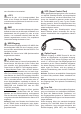
www.audiotec-fischer.com. Please note: It is not possible to connect any USB storage devices. 8 Control pushbutton The UP 10DSP provides 10 internal memory locations for sound setups. The Control pushbutton allows the user to switch between two memory positions. These can be defined in the DSP PC-Tool. 1. Setup switch: Press Control pushbutton for 1 second. The memory locations one and two are defined ex works. Switching is indicated by a single red flash of the Status LED.
Initial start-up and functions 13 Status LED The Status LED indicates the operating mode of the amplifier and of the DSP memory. Green: Amplifier is ready for operation. Orange: Power Save Mode is active. Red: Protection Mode is active. This may have different root causes. The amplifier is equipped with protection circuits against over- and undervoltage as well as overheating. Please check for connecting failures such as short-circuits or other wrong connections.
Fig. 3: Pin configuration UP 10DSP SPEAKER OUTPUT HIGHLEVEL INPUT SYSTEM CONNECTOR 29 30 31 32 33 34 21 22 23 24 1 35 36 37 38 39 40 25 26 27 28 11 12 13 14 15 16 17 18 19 20 2 3 4 5 6 7 REM IN 8 9 POWER INPUT +12V GND 10 OUT System Connector 1. Highlevel loudspeaker input rear left (-) / C 2. Highlevel loudspeaker input front left (-) / A 3. Highlevel loudspeaker input front right (-) / B 4. Highlevel loudspeaker input rear right (-) / D 5. Loudspeaker output rear right (-) / D 6.
Installation The MATCH UP 10DSP must be installed and connected as follows: ery or an appropriate cable harness from the MATCH accessories program for connection! Caution: Carrying out the following steps will require special tools and technical knowledge. In order to avoid connection mistakes and / or damage, ask your dealer for assistance if you have any questions and follow all instructions in this manual (see page 28). 2.
4. Adjustment of the input sensitivity Attention: It is mandatory to properly adapt the input sensitivity of the UP 10DSP to the signal source in order to avoid damage to the amplifier. The input sensitivity can be adjusted via the DSP PC-Tool software and by changing the position of a jumper inside the device. The setting will be undertaken in two steps: 1. Pre-adjustment of the value range using the jumper inside the device. 2. Exact adjustment of the input sensitivity by using the DSP PC-Tool software.
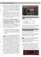
Installation 4. If the clipping indicator in the DSP PC-Tool already lights up (see picture below), you have to reduce the input sensitivity using the scroll bar until the indicator turns off. 5. Increase the input sensitivity until the clipping indicator lights up. Now turn the control back until the indicator turns off again. Various adjustment examples of the input sensitivity can be found on page 37. For further applications please contact your MATCH specialist dealer. 5.
ers must not be lower than 4 Ohms for channel E - H and 2 Ohms for channel I and J, otherwise the amplifier protection will be activated. Attention: Solely use the connection cable with the 12-pole connector and flying leads which is included in delivery for connecting further loudspeakers or an appropriate cable harness from the MATCH accessories program! 10.
Configuration examples Example 1: Channel routing with Virtual Channel Processing 4-channel head unit > Front: 3-way fully active; Rear: 2-way fully active + Line Out for external subwoofer From car radio Inputs Virtual channels Front L Full (A) SFX Front Processing Front L Full Front R Full Rear L Full Rear R Full Input A Input B Input C Input D Summen signal A bis D Front R Full (B) SFX Front Processing Rear L Full (C) Rear R Full (D) Subwoofer 1 (K) SFX Augmented Bass Processing Outputs To spea
Example 3: 9-channel 1 to 1 channel routing (IOR) e.g.
Connection to a PC It is possible to freely configure the UP 10DSP with our DSP PC-Tool software. The user interface is designed for easy handling of all functions and allows an individual adjustment of each of the 11 DSP channels. Prior to connecting the amplifier to your PC visit our website and download the latest version of the DSP PC‑Tool software. Check from time to time for software updates. You will find the software and a huge knowledge base at www.audiotec-fischer.com.
Virtual Channel Processing (VCP) Operating concept of the VCP In opposite to previous methods the Virtual Channel Processing (VCP) is a multi-stage signal processing concept that enables the perfect configuration of complex sound systems, opening up completely new possibilities for sound tuning. The function extends the previous scope of the device by an additional layer of processed channels, which is located between the inputs and outputs.
Virtual Channel Processing (VCP) – Cross-channel group equalizer Example application: Active multi-way speaker configuration If an input signal (e.g. front left) is first routed to a virtual channel (Front L Full) and this signal is then routed to an active multi-way system (e.g. front left – tweeter, midrange and woofer), the group equalizer of the virtual channel will influence all assigned output channels in their tonality.
Configuration of the Virtual Channel Processing (VCP) To configure the VCP, you first have to enable “Virtual Channel Processing” in the DCM menu of the DSP PC-Tool software. Therefore, go to the “Virtual Channel Processing” tab in the DCM menu and click on the right box with the VCP graphic. Then the configuration will be carried out in two steps. Here’s an example of a 3-way configuration with a 2-way input signal.
Configuration of the Virtual Channel Processing (VCP) Workflow step 2 – Output routing After all the input signals used in the respective signal routing matrix have been configured, the virtual channels must now be assigned to the physical output channels. Here, a virtual signal (e.g. Front L Full) can be assigned to multiple outputs, such as “front left” tweeter, midrange and woofer.
Workflow step 3 – Configuration of the virtual channels and notes on the application of the DSP sound effects (SFX) Now switch to the “Virtual” menu of the DSP PC-Tool. Here you get an overview of the signal flow of the individual channels and the activated sound effects. In addition, it is possible to influence the tonality of all subsequent output channels of a virtual channel at the same time, for example with the help of the equalizer, polarity and other functions.
Configuration of the Virtual Channel Processing (VCP) 2. Change to the “Virtual to Output Routing” matrix and route the “Virtual E – Front Center Full” channel to the desired output channels (as described in workflow step 2) to which the center processing shall be applied. For information about input routing see workflow step 1 3. Now switch to the FX menu and activate the desired sound effect in the “Center Processing” tab by setting the appropriate check mark.
Configuration of a subwoofer remote control First, the appropriate remote control must be activated in the “Extended Features” tab in the DCM menu of the DSP PC-Tool software and configured, depending on the model. If the VCP is not activated, the subwoofer remote control of the UP 10DSP is permanently assigned to the output channels I and J. In this case it does not matter which output is named “Subwoofer” in the IO routing matrix.
ACO platform features Beside the unique DSP sound effects the UP 10DSP provides a bunch of new system features. In the DCM menu of the DSP PC-Tool software individual settings can be made for several of these system features. Turn On & Off Delay This function allows to determine the delay time with which the integrated DSP is switched on and off. The factory setting is 0.2 seconds. The delay time should only be modified if there are e.g. noises while switching on / off the amplifier.
Unique Features of the UP 10DSP Class GD technology Audiotec Fischer´s proprietary Class GD concept takes the efficiency of conventional Class D amps to the next level. By varying the internal supply voltage in several steps depending on the amplifier’s input signals, idle losses are significantly reduced and overall efficiency is close to maximum at any time. So heat dissipation is almost negligible, thus allowing smallest heat sinks and most compact form factors.
Installation of a MATCH Extension Card It is possible to extend the functionality of the MATCH UP 10DSP amplifier by adding further interfaces like a Bluetooth® Audio Streaming module, a High Resolution Audio USB soundcard etc. To install a MATCH Extension Card it is necessary to remove the side panel of the UP 10DSP and replace it by the new side panel that comes with the MEC module. 6. Make sure that the MEC module is installed properly and all pins are fully inserted into the socket.
Technical Data Output power RMS - Channel A - H..................................................................... 8 x 65 Watts @ 4 Ohms - Sub Out I - J....................................................................... 2 x 90 Watts @ 4 Ohms 2 x 160 Watts @ 2 Ohms Amplifier technology............................................................. Class GD Inputs....................................................................................
Audiotec Fischer GmbH Hünegräben 26 · 57392 Schmallenberg · Germany Tel.: +49 2972 9788 0 · Fax: +49 2972 9788 88 E-mail: match@audiotec-fischer.com · Internet: www.audiotec-fischer.