
Owner's Manual


29
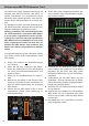
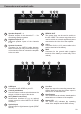
Connectors and control units
1
Speaker Output E - J
Speaker outputs of the channels E - J for
connecting speaker systems.
2
Highlevel Input E - H
Highlevel speaker inputs of the channels
E - H.
3
System Connector
Connector for the MATCH cable harness.
Make sure that you only use a MATCH origi-
nal connection cable to connect the amplier
to the car radio.
4
REM IN / OUT
The remote input can be used to switch on
the UP 10DSP. The remote output has to be
used to switch on external ampliers that are
connected to the Line Out of the amplier.
5
+12 V
Connector for the +12 V power cable to the
positive terminal of the battery.
6
GND
Connector for the ground cable (negative
terminal of the battery or metal body of the
vehicle).
1 2 3 4 5 6
7
USB Input
Connects the UP 10DSP to your PC.
8
Control pushbutton
Use this button to either switch between the
setups or initiate a reset of the device.
9
SCP (Smart Control Port)
Multifunction interface for e.g. an optional
remote control or other MATCH UP 10DSP
accessory.
10
Optical Input
Optical input for digital stereo signals (SPDIF
format).
11
Line Out
Mono line output for connecting external am-
pliers. Make sure that the remote output is
used to turn on these devices.
12
Auto Remote
This switch allows to activate / deactivate the
automatic turn-on feature of the amplier
.
13
Status LED
The Status LED indicates the operating
mode of the amplier and its DSP memory.
13
7 8 9 10 11 12