
Owner's Manual


32
Installation
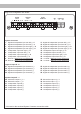
Fig. 1: Overview connection cables
1
System Connector connection cable
2
Speaker Output E - J connection cable
3
Highlevel Input E - H connection cable
4
Remote (REM IN / OUT) connection cable
1 2 3
Fig. 2: Pin assignment Power Input plug
Plug top side
A
+12 V – for connecting the UP 10DSP to the positive
terminal of the car´s battery.
B
GND – for connecting the ground cable.
4
A
B
13
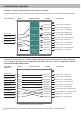
Status LED
The Status LED indicates the operating mode of the
amplier and of the DSP memory.
Green: Amplier is ready for operation.
Orange: Power Save Mode is active.
Red: Protection Mode is active. This may have dif-
ferent root causes. The amplier is equipped with
protection circuits against over- and undervoltage
as well as overheating. Please check for connecting
failures such as short-circuits or other wrong con-
nections.
If the amplier is overheated the internal tempera-
ture protection switches o the remote and signal
output until it reaches a safe temperature level
again.
Red / green slow ashing: No operating soft-
ware installed. Connect the amplier to the DSP
PC-Tool software and conrm the automatic up-
date of the operating system. You will nd the
latest version of the DSP PC-Tool software at
www.audiotec-scher.com.
Red / green fast ashing: The currently selected
sound setup memory is empty. A new setup has to
be loaded via the DSP PC-Tool software or switch
to a memory position with existing sound setup.
Initial start-up and functions