
Owner's Manual


36
Installation
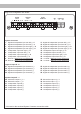
4. If the clipping indicator in the DSP PC-Tool
already lights up (see picture below), you
have to reduce the input sensitivity using the
scroll bar until the indicator turns o.
5. Increase the input sensitivity until the clip-
ping indicator lights up. Now turn the control
back until the indicator turns o again.
Various adjustment examples of the input
sensitivity can be found on page 37. For
further applications please contact your
MATCH specialist dealer.
5. Connection to power supply
Make sure to disconnect the battery before
installing the MATCH UP 10DSP!
Connect the +12 V power cable to the positive
terminal of the battery. The positive wire from
the battery to the amplier power terminals
needs to have an inline fuse (50 A) at a distance
of less than 12 inches (30 cm) from the battery.
If your power wires are short (less than 1 m /
40”) then a wire gauge of 6 mm² / AWG 10 will
be sucient. In all other cases we strongly rec-
ommend gauges of 10 - 16 mm² / AWG 8 – 6!
The ground cable (same gauge as the +12 V
wire) should be connected to a common ground
reference point (this is located where the neg-
ative terminal of the battery is grounded to the
metal body of the vehicle) or to a prepared met-
al location on the vehicle chassis, i.e. an area
which has been cleaned of all paint residues.
Attention: Solely use the Power Input plug
which is included in delivery for connection (see
page 31, g. 2).
6. Connecting the remote input
The remote input (REM IN) has to be connect-
ed to the radio remote output if the ampliers
Optical Input is solely used as signal input. We
do not recommend controlling the remote input
via the ignition switch to avoid pop noise during
turn on / o.
If one of the highlevel inputs A - H is used this
input does not need to be connected as long as
the car radio has BTL output stages.
7. Conguration of the remote input
The UP 10DSP will be turned on automatically
if the highlevel inputs are used or if a remote
signal is applied to the remote input terminal
(REM IN). The Auto Remote switch (page 31,
point 12) allows to deactivate the automat-
ic turn-on feature of the highlevel inputs. The
feature should be deactivated if there are e.g.
disturbing noises while switching on / o the
amplier.
Note: If the automatic turn-on function is deac-
tivated it is mandatory to use the remote input
terminal to power up the amplier! The highlevel
signal will be ignored in this case.
To deactivate the automatic turn-on feature you
have to change the position of the Auto Remote
switch to “O”.
8. Conguration of the internal DSP
The general amplier settings should be
conducted with the DSP PC-Tool software
before using the amplier for the rst time.
Ignoring this advice may result in damaging the
connected speakers / ampliers. Especially if
the UP 10DSP will be used to drive fully active
speaker systems, a wrong setup can destroy
your tweeters right away.
Information on connecting the UP 10DSP to a
computer can be found on page 40.
9. Connecting the speaker outputs E - J
The loudspeaker outputs allow to connect
speaker systems using the included connection
cable as well as subwoofers to the two power
channels I & J (see page 33, g. 3, no. 29 - 40).
Never connect any of the loudspeaker cables
with the chassis ground as this will damage
your amplier and your speakers. Ensure that
the loudspeakers are correctly connected (in
phase), i.e. plus to plus and minus to minus. Ex-
changing plus and minus causes a total loss of
bass reproduction. The plus pole is indicated on
most speakers. The impedance of the speak-