
Owner's Manual


37
For further applications please contact your MATCH specialist dealer.
Examples for adjusting the input sensitivity of the channels G & H:
Source Jumper position
Input Gain in DSP PC-Tool
OEM-Radio
Up to 25 Watts RMS power per
channel at 4 Ohms or up to 50 Watts
RMS power at 2 Ohms
Low voltage range (J 1) –
Ex factory jumper position
(see g. 1)
OEM-Radio with additional
amplier
>25 Watts and up to 200 Watts RMS
power at 4 Ohms or up to 100 Watts
RMS power per channel at 8 Ohms
High voltage range (J 2)
(see g. 2)
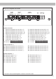
Figure 1:
Voltage range 4 - 16 Volts
Figure 2:
Voltage range 8 - 32 Volts
ers must not be lower than 4 Ohms for channel
E - H and 2 Ohms for channel I and J, other-
wise the amplier protection will be activated.
Attention: Solely use the connection cable with
the 12-pole connector and ying leads which is
included in delivery for connecting further loud-
speakers or an appropriate cable harness from
the MATCH accessories program!
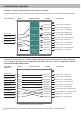
10. Connecting the remote output
This output (REM OUT) is used to supply re-
mote signals to additional ampliers that are
connected to the Line Out of the UP 10DSP.
Always use this remote output signal to turn on
the ampliers in order to avoid on / o switching
noises.
J 2
J 1