
Owner's Manual


44
Conguration of the Virtual Channel Processing (VCP)
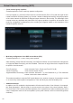
Workow step 2 – Output routing
After all the input signals used in the respective signal routing matrix have been congured, the virtual
channels must now be assigned to the physical output channels. Here, a virtual signal (e.g. Front L Full)
can be assigned to multiple outputs, such as “front left” tweeter, midrange and woofer. The conguration of
these speaker-specic output channels is done in the “Outputs” menu (called “Main” in normal mode) of the
DSP PC-Tool. Here you can also congure the channel-specic equalizers, high- and lowpass lters, time
alignment, output level and phase settings.
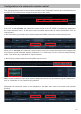
a. In order to assign the virtual channels to the respective output channels the individual virtual signals in
the output routing matrix (“Virtual to Output Routing”) are dragged and dropped onto the output chan-
nels. At this point, the signals typically needn’t to be summed, means that each output of this matrix only
receives one virtual signal. For example, the output “Front L High” is linked to the virtual signal “Front L
Full”; the same is done for the Front L Low”.
b. At this point, even a virtual channel in which a DSP sound eect has been activated can be routed to
multiple output channels. For example, the “Front Center Full” signal can be assigned to multiple output
channels to create an active multi-way center speaker. The corresponding high- and lowpass lters are
then congured in the output channels of the “Main” menu.