PNP3 SHUTTLE Vehicle Installation Guide SIR-CK3 s.seek 001 p.
THIS PAGE LEFT BLANK INTENTIONALLY -2- 128-7194 2 of 20
CONTENTS Congratulations ........................................................................................ 4 Cautions and Warnings ............................................................................ 5 Contents SIR-CK3 ................................................................................... 6 Hardware Kit ................................................................................. 6 Installation/Wiring Precautions ...............................................................
Congratulations You are one step closer to experiencing Sirius Satellite Radio. Sirius will revolutionize your in-home or vehicle entertainment with: • Over 120 channels of original programming, including – 65 channels of 100% commercial-free music – guaranteed, Over 50 channels of world-class sports, news, talk and information. Your Model PNP3 Audiovox Shuttle must be used with an adapter kit, such as the Audiovox Home kit, Boom Box or Vehicle Kit as required by your specific installation needs.
Cautions and Warnings 1. Do not install the Shuttle in a position that hinders your view through the windshield, or obstructs view ing of the dashboard indicators and displays. 2. Do not install the unit where it may obstruct the operation or deployment of safety devices, such as airbags, etc. 3. Do not allow operation of the unit to detract from safe driving practices; remember that you are responsible as the vehicle operator to adhere to all safe driving and traffic regulations. 4.
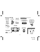
Contents SIR-CK3 Install Manual (P/N 1287194) Antenna (P/N 118-1135) Base (P/N 136-3804) HARDWARE KIT Audio Cable (Optional) (P/N SAT-RCA) (P/N 150-1577) 1.6” W X 2”Long Double Sided Foam Tape (P/N 138-1305) Phillips Machine Screw (M4 x 8mm) With Captive Lock and Flat Washer (P/N 100-2329) 1 pc. 1 pc. 1 pc Cradle CK3 (P/N 136-3801) 4 pcs. Alcohol Swab (P/N 138-1189) 1 pc. OPTIONAL FM Switching Box Assy P/N SAT-SWB (6 Meter) DC Power Adapter (P/N 112-3459) 1 pc. 1 pc. 1 pc. 1 pc.
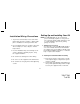
Installation/Wiring Precautions 1. To prevent a short-circuit, be sure to turn off the ignition and remove the negative (-) battery cable prior to installation. Connect power wires last. Setting Up and Installing Your Kit NOTE: The SIRIUS® signal can be received and processed virtually anywhere as long as there are no obvious satellite signal obstructions such as nearby buildings, high terrain, parking garages or tunnels. 1.
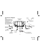
Interconnect Diagram NOTE: SHUTTLE CRADLE CK3 (REAR VIEW) 1. THE FM TRANSMITTER OPTION MUST BE SET TO ”FM ON” IN THE SHUTTLE USER MENU. (REFER TO THE OWNER’S MANUAL, PUBLICATION NO.128-7193.) 2. IF THE SIR-CK3 IS INSTALLED USING THE WIRELESS FM SWITCHING BOX, SAT-SWB, OPTION, DO NOT CONNECT THE AUDIO CABLE TO THE LINE OUT CONNECTOR OF THE CRADLE.
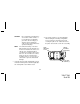
CAUTION: NOTE: Do not install the mounting base on a leather or fabric surface, or in a position that could impair your vision, block air bag(s) or obstruct vehicle dashboard controls and/or radio CD/casette operational displays. The adhesive backing on the base will not permit easy repositioning once it has been mated to the surface; use extreme care and planning when selecting the mounting location.
BASE ASSEMBLY MOUNTING PLATE e. If the outside air temperature is cold, it may be beneficial to warm the adhesive backing on the base using a portable hair dryer, or by holding the backing surface in front of a vehicle heater vent. SCREW HOLES (4) FOR DIRECT HARD MOUNTING f.
NOTE: Allow a 72-hour period for the adhesive backing to cure completely. 3. Installing the Cradle Using Double-Sided Tape You can mount the cradle directly to your dashboard or other flat surface without using the cradle mount in the kit. To do this, do not remove the mounting plate assembly from the cradle. a. Remove the 3/4” x 3” double-sided tape from the supplied kit. b. Determine the location of the cradle, and clean the mounting surface as before. c.
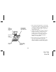
LATCH TAB LOCK/UNLOCK LEVER CRADLE TOP VIEW SHUTTLE REAR VIEW SHUTTLE LATCHING TAB 20-PIN SYSTEM CONNECTOR SHUTTLE LATCHING TAB RECESS LATCH TAB LOCK/UNLOCK LEVER CONNECTOR GUIDE PIN CRADLE FRONT VIEW SHUTTLE REAR SPINE GROOVES CRADLE REAR VIEW CRADLE GUIDE SPINES b. After making sure the connectors are properly lined up, gently press down on the shuttle to mate the connectors together. c.
6. Sirius Program Listening Options The Shuttle and Cradle provide an audio output signal in three manners: 1. When using the SIR-CK3 cradle with the FM switching box option, the audio signal can be transmitted to a car radio on one of over 100 selectable FM frequencies using the menu options included in your PNP3 shuttle. (Refer to the shuttle owner’s manual.) The audio signal can then be played through your car radio when the car radio is tuned to one of these frequencies.
7. Mounting the Vehicle Antenna The antenna should be placed on a relatively flat surface on the vehicle exterior, preferably on the roof (high point) or on the trunk (convertible). To mount the antenna: a. Plug the antenna into the ANT connector on the back of the cradle. b. Place the antenna at the preferred location on the roof or trunk surface. If the vehicle is equipped with a roof or trunk rack, the antenna may have to be mounted off-center on the surface.
e. Plan the routing of the antenna cable to the Shuttle RF input. Make sure you avoid any obstructions that could crimp, kink or twist the cable; use protective grommets wherever rough openings are encountered. f. Route the cable from the antenna position to the interior of the vehicle, working the cable under the rear window molding; make adjustments and take up slack whenever necessary. g.
i. Plug the antenna cable into the ANT connector on the back of the cradle; then plug the cigarette lighter adapter into the lighter receptacle. The integral power LED of the power button ( ) will light red. j. You are now ready to enjoy Sirius programming within your vehicle. CAUTION: You could drain the vehicle battery if the cigarette lighter adapter remains plugged in after the ignition is turned off. Unplug the adapter to prevent this possibility.
THIS PAGE LEFT BLANK INTENTIONALLY -17- 128-7194 17 of 20
12 MONTH LIMITED WARRANTY AUDIOVOX CORPORATION (the Company) warrants to the original retail purchaser of this product that should this product or any part thereof, under normal use and conditions, be proven defective in material or workmanship within 12 months from the date of original purchase, such defect(s) will be repaired or replaced with new or reconditioned product (at the Company's option) without charge for parts and repair labor.
THIS PAGE LEFT BLANK INTENTIONALLY -19- 128-7194 19 of 20
© 2004 Audiovox Electronics Corporation, 150 Marcus Blvd.